Owner’s Manual
Blackstar Amplification Ltd, Beckett House, 14 Billing Road, Northampton, NN1 5AW, UK
For the latest information go to: www.blackstaramps.com
Whilst the information contained herein is correct at the time of publication, due to our policy of constant improvement
and development, Blackstar Amplification Ltd reserves the right to alter specifications without prior notice.
Designed and Engineered by
Blackstar Amplification UK
190403M-1 08/20
&

3
USA / Canada
IMPORTANT SAFETY INSTRUCTIONS
1. Read these instructions.
2. Keep these instructions.
3. Heed all warnings.
4. Follow all instructions.
5. Do not use this apparatus near water.
6. Clean only with dry cloth.
7. Do not block any ventilation openings.
8. Install in accordance with the manufacturer’s instructions.
9. Do not install near any heat sources such as radiators, heat registers, stoves, or
other apparatus (including ampliers) that produce heat.
10. Do not defeat the safety purpose of the polarized or grounding-type plug. A
polarized plug has two blades with one wider than the other. A grounding type
plug has two blades and a third grounding prong. The wide blade or the third
prong are provided for your safety. If the provided plug does not t into your
outlet, consult an electrician for replacement of the obsolete outlet.
11. Protect the power cord from being walked on or pinched particularly at plugs,
convenience receptacles, and the point where they exit from the apparatus.
12. Only use attachments/accessories specied by the manufacturer.
13. Unplug this apparatus during lightning storms or when unused for long periods
of time.
14. Refer all servicing to qualied service personnel. Servicing is required when the
apparatus has been damaged in any way, such as power-supply cord or plug is
damaged, liquid has been spilled or objects have fallen into the apparatus, the
apparatus has been exposed to rain or moisture, does not operate normally, or
has been dropped.
“TO COMPLETELY DISCONNECT THIS APPARATUS FROM THE AC MAINS,
DISCONNECT THE POWER-SUPPLY CORD PLUG FROM THE AC RECEPTACLE”.
“WARNING: TO REDUCE THE RISK OF FIRE OR ELECTRIC SHOCK, DO NOT
EXPOSE THIS APPARATUS TO RAIN OR MOISTURE. THE APPARATUS SHALL
NOT BE EXPOSED TO DRIPPING OR SPLASHING AND THAT OBJECTS FILLED
WITH LIQUIDS, SUCH AS VASES, SHALL NOT BE PLACED ON APPARATUS".
This symbol is intended to alert the user to the presence of
uninsulated “dangerous voltage” within the product’s enclosure that
may be of sucient magnitude to constitute a risk of electric shock
to persons.
This symbol is intended to alert the user to the presence of important
operation and maintenance (servicing) instructions in the literature
accompanying the appliance.
English
5
English
4
Never disconnect the protective mains earth connection.
High loudspeaker levels can cause permanent hearing damage. You should
therefore avoid the direct vicinity of loudspeakers operating at high levels. Wear
hearing protection if continuously exposed to high levels.
If the product does not operate normally when the operating instructions are
followed, then refer the product to a qualied service engineer.
The U.S. Government's Occupational Safety and Health Administration (OSHA) has
specied the following permissible noise level exposures:
Duration Per Day In Hours Sound Level dBA, Slow Response
8 90
6 92
4 95
3 97
2 100
1½ 102
1 105
½ 110
¼ or less 115
According to OSHA, any exposure in excess of the above permissible limits could
result in some hearing loss.
Ear plug protectors in the ear canals or over the ears must be worn when operating
this amplication system in order to prevent a permanent hearing loss if exposure is
in excess of the limits as set forth above. To ensure against potentially dangerous
exposure to high sound pressure levels, it is recommended that all persons
exposed to equipment capable of producing high sound pressure levels such as
this amplication system be protected by hearing protectors while this unit is in
operation.
Warning!
Important safety information!
READ THE FOLLOWING INFORMATION CAREFULLY. SAVE ALL
INSTRUCTIONS FOR FUTURE REFERENCE!
Follow all warnings and instructions marked on the product!
Danger! High internal operating voltages.
Do not open the equipment case. There are no user serviceable parts in this
equipment. Refer all servicing to qualied service personnel.
Clean only with a dry cloth.
Condensation can form on the inside of an amplier if it is moved from a cold
environment to a warmer location. Before switching the unit on, it is recommended
that the unit be allowed to reach room temperature.
Unauthorised modication of this equipment is expressly forbidden by Blackstar
Amplication Ltd.
Never push objects of any kind into ventilation slots on the equipment casing.
Do not expose this apparatus to rain, liquids or moisture of any type.
Do not place this product on an unstable trolley, stand or table. The product may
fall, causing serious damage to the product or to persons!
Do not cover or block ventilation slots or openings. This unit must only be used in
a well ventilated area and never switched on when it is within a poorly ventilated
space, such as a bookcase.
This product should not be placed near a source of heat such as a stove, radiator,
or another heat producing amplier.
Use only the supplied power cord which is compatible with the mains voltage supply
in your area.
Power supply cords should always be handled carefully and should be replaced if
damaged in any way.
Never break o the earth (ground) pin on the power supply cord.
The power supply cord should be unplugged when the unit is to be unused for long
periods of time.
An apparatus with Class I construction should be connected to a mains socket
outlet with a protective earthing connection.
The mains plug of the power supply cord should remain readily accessible.
Before the unit is switched on, the loudspeaker should be connected as described
in the handbook using the lead recommended by the manufacturer.
Always replace damaged fuses with the correct rating and type.
All electrical and electronic products should be disposed of separately
from the municipal waste stream via designated collection facilities
appointed by the government or the local authorities.

Features
Blackstar’s Live Logic USB MIDI footcontroller is the result of countless hours of
technical research and benchmarking against market leading products. Designed
from the ground up for musicians and producers, they are feature filled and compact.
The Live Logic USB MIDI footcontroller gives you quick and easy performance
control of any MIDI hardware or software platforms and plugins. Seamlessly send
program change messages and map parameter controls to any of the switches,
or assign continuous control of any MIDI parameter to an expression pedal using
the two expression pedal inputs (expression pedal not included). MIDI over USB is
also included for use with DAWs, plugins and live sequencer/ sampling software
like Ableton Live™.
This product comes with a free downloadable copy of Ableton’s powerful Live Lite
10 Lite software. Although an excellent software, you have total freedom to use and
control an array of Midi products with your own preferred software.
Power your Live Logic USB Midi Footcontroller anywhere via USB, 9V battery or
power supply.
Free Ableton Live Lite licence
Ableton Live Lite 10 Software
Blackstar have teamed up with Ableton Live to create a customised control surface
script and your Live Logic MIDI Footcontroller includes a free copy of Ableton’s
excellent Live Lite 10 Lite software. You can use all of Live 10 Lite’s essential
workflows, instruments and effects to record songs, create hands-on with your
controller, take music made in your apps further and much more.
Please read the ‘Ableton Mode’ section below for specific information on this feature.
Click here to download your free Ableton Live Lite software:
https://www.blackstaramps.com/uk/ableton
English
7
Introduction
Thank you for purchasing this Blackstar Live Logic USB MIDI Footcontroller.
Like all our products, the Live Logic Footcontroller is the result of countless hours of
painstaking Research and Development by our world-class design team. Based in
Northampton (UK), the Blackstar team are all experienced musicians themselves and
the sole aim of this development process was to provide musicians and producers
with products which are the ultimate tools for self-expression.
All Blackstar products are subjected to extensive laboratory and road testing to
ensure that they are truly uncompromising in terms of reliability, quality and above
all TONE.
Please read through this handbook carefully to ensure you get the maximum benefit
from your new Blackstar product.
If you like what you hear and want to find out more about the Blackstar range of
products please visit our website at www.blackstaramps.com.
Thanks!
The Blackstar Team
English
6
Switching to the Right/ ‘CUSTOM’ allows you to use the Blackstar Live Logic Midi
control software via USB to customise the MIDI messages being sent via MID cable
and USB. Map any of the following message types to the six footswitches:
Program Change
Control Change
Note
Clock
Note
7 & 8. The Live Logic Footcontroller can be powered by either USB from your PC/
Mac, a suitable 9V battery or Blackstar’s compact PSU-500 (sold separately) which
operates from 100-240V AC and comes with 4 different plug fittings, making it
usable in many countries around the world.
9. Pushing the power button ‘in’ will turn the unit on, illuminating the front LED panel.
Pressing the button again to the ‘out’ position will shut the Live Logic Footcontroller
off immediately.
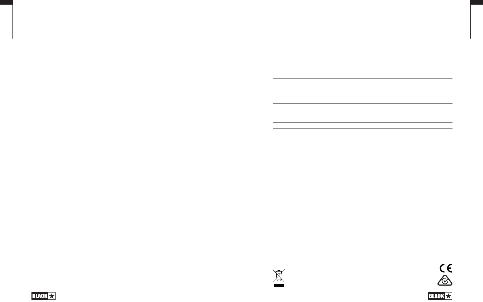
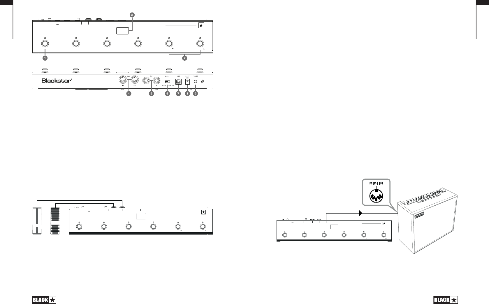
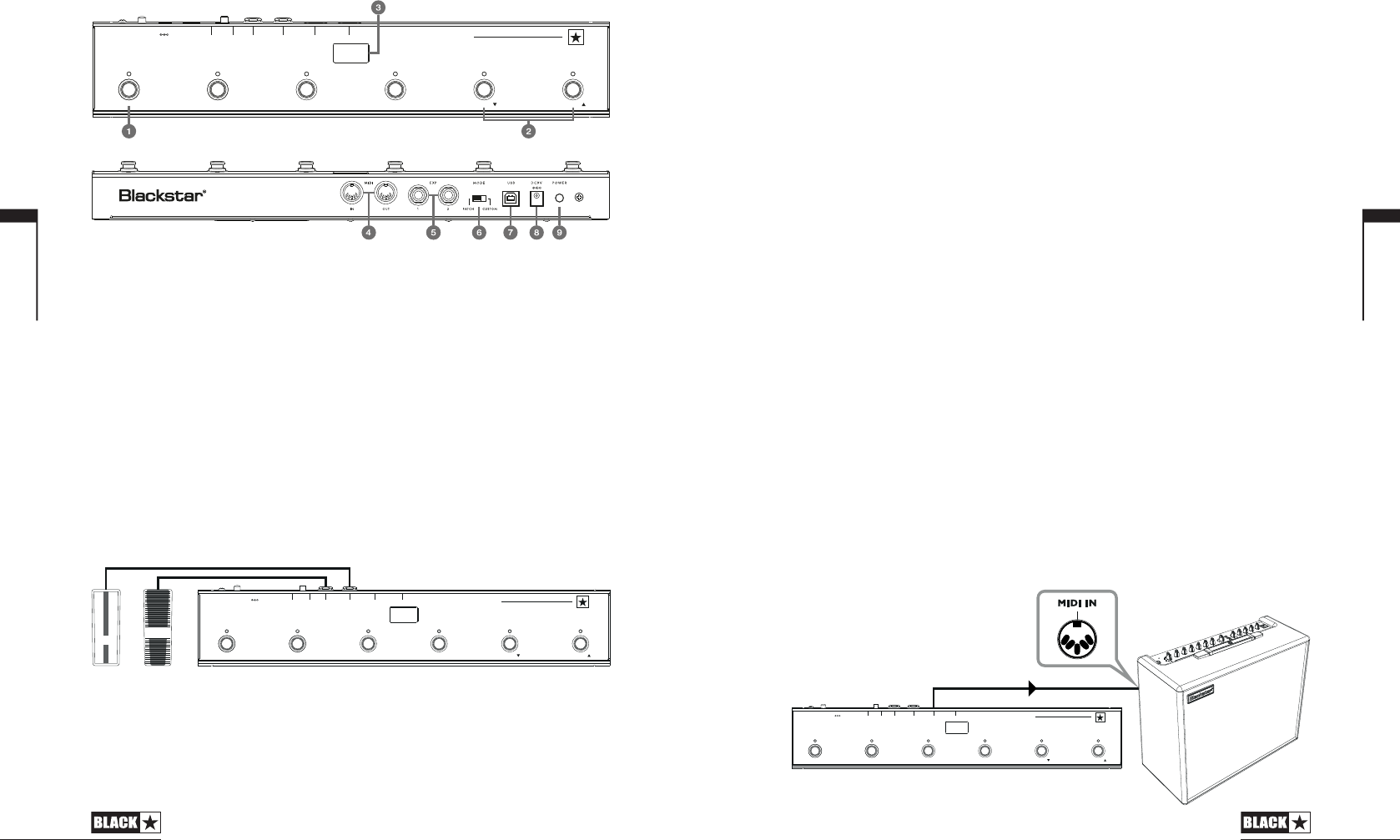
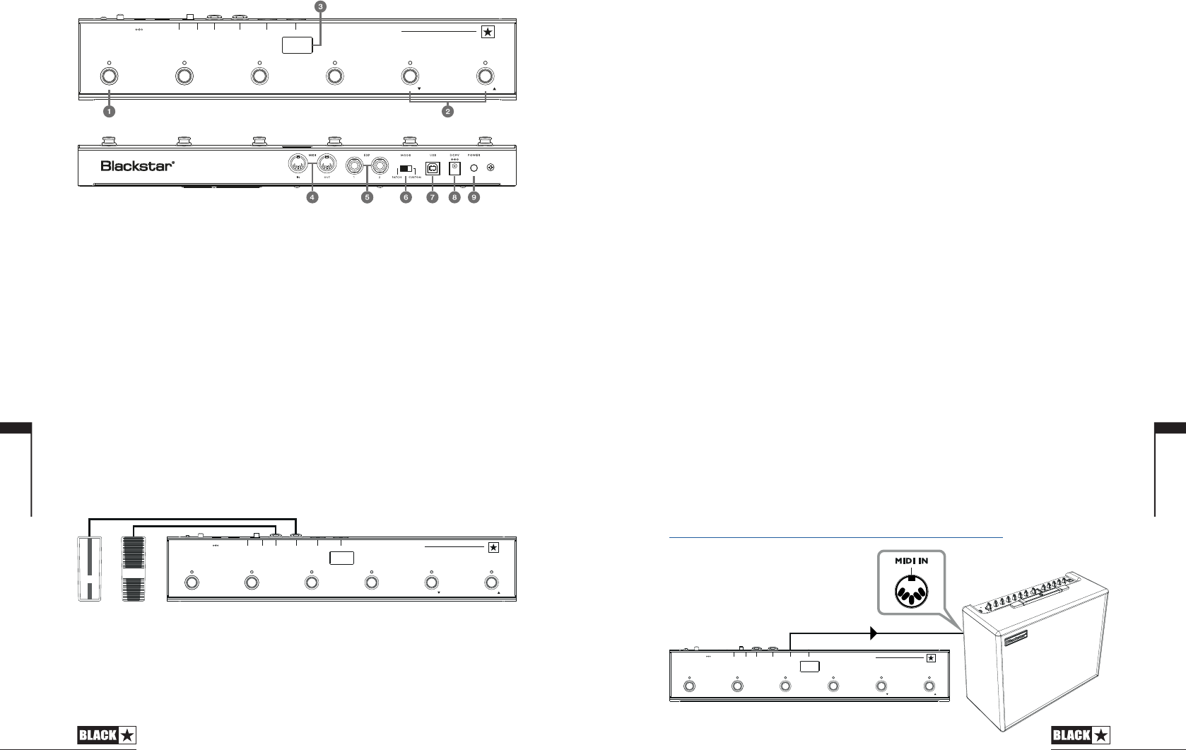
Examples of correct setup with specific products
Blackstar Silverline
Live Logic MIDI output Silverline MIDI input
Patch mode - changing patch on your Silverline (Set patch mode display to offset)
Custom mode Download the Silverline Template from
https://www.blackstaramps.com/uk/ranges/live-logic/usb-midi-controller for an
example of MIDI Mapping.
English
9
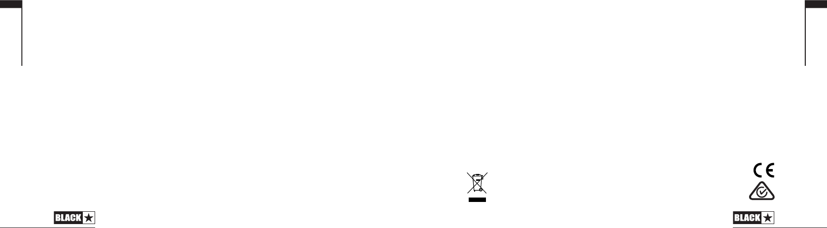
Live Logic product buttons and features
Front Panel (In Patch Mode)
1. 6 individual footswitches with independent corresponding LEDs that tell you the
current selected footswitch once pressed.
2. ‘Footswitch 5’ controls ‘Bank down’ and ‘Footswitch 6’ selects ‘Bank up’.
3. Stage-visible front facing LED display. Once the unit is powered on the LED
display will illuminate.
Rear Panel
4. 2 MIDI In/ Out sockets allow you to connect MIDI hardware using standard 5 pin
DIN cables.
5. Two individual expression pedal inputs allow you to connect up to two pedals
at a time. These can be programmed using the USB control software.
6. MODE select switches between ‘PATCH’ and ‘CUSTOM’ modes.
Switching the MODE switch to the Left/ ‘PATCH’ will allow you to send Program
Change (PC) messages to any connected MIDI device(s) via MIDI cable or USB.
Program range (0-127/1 - 128) can be selected via the USB control software
Switches 1 - 4: Send corresponding Program Change message, in banks of 4
Switch 5: Bank down
Switch 6: Bank up
English
8
BA N K BA N K
5 61 2 3 4
P OW ER D C9V U SB M ODE
PAT CH OU T INCU ST OM 2 1
E XP M IDI
C U S T O M U S B M I D I C O N T R O L
L I V E L O G I C
BA NK BA NK
5 61 2 3 4
PO WE R DC 9V U SB MO DE
PAT CH OU T I NCU STO M 2 1
EX P MI DI
C U S T O M U S B M I D I C O N T R O L
L I V E L O G I C
BA NK BA NK
5 61 2 3 4
PO WER D C9 V USB MO DE
PATC H OU T INCU STO M 2 1
EX P MI DI
C U S T O M U S B M I D I C O N T R O L
L I V E L O G I C
Blackstar Series One
Live Logic MIDI output Series One MIDI input
Patch mode - changing channel on your Series One (Set patch mode display
to offset)
Custom mode Download the Series One Template from
https://www.blackstaramps.com/uk/ranges/live-logic/usb-midi-controller to
change patch with two switches left blank for other MIDI equipment.
DAW plugin control
Live Logic USB ---> PC/MAC
English
10
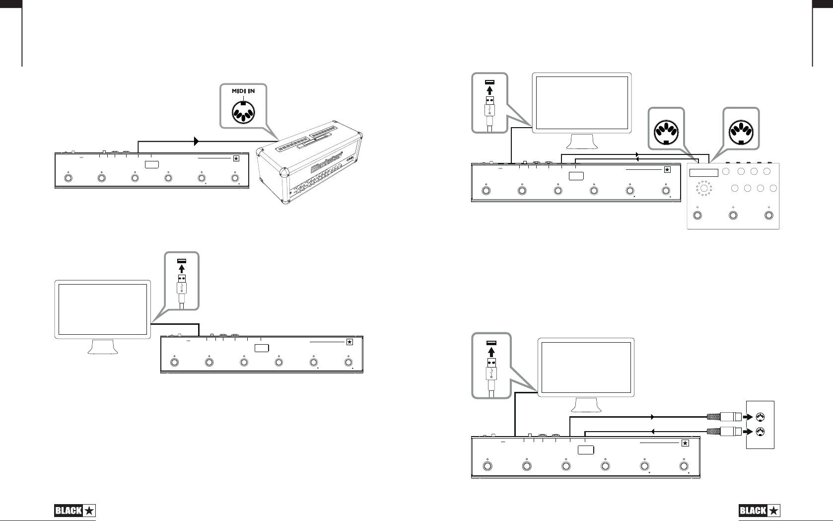
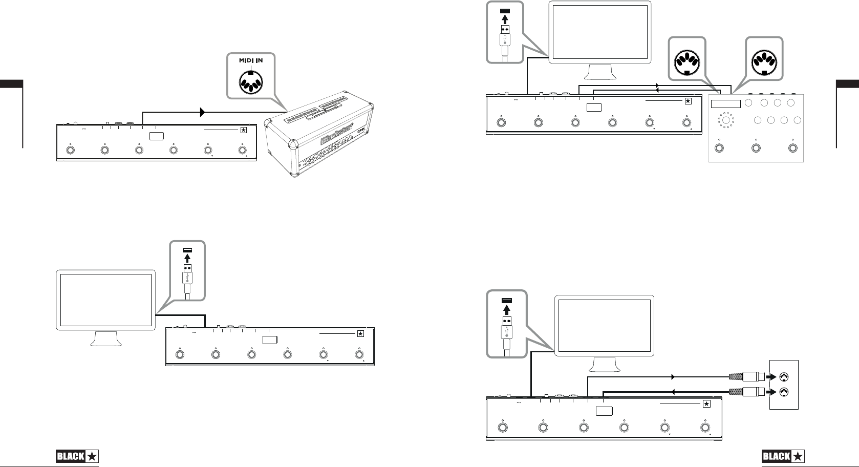
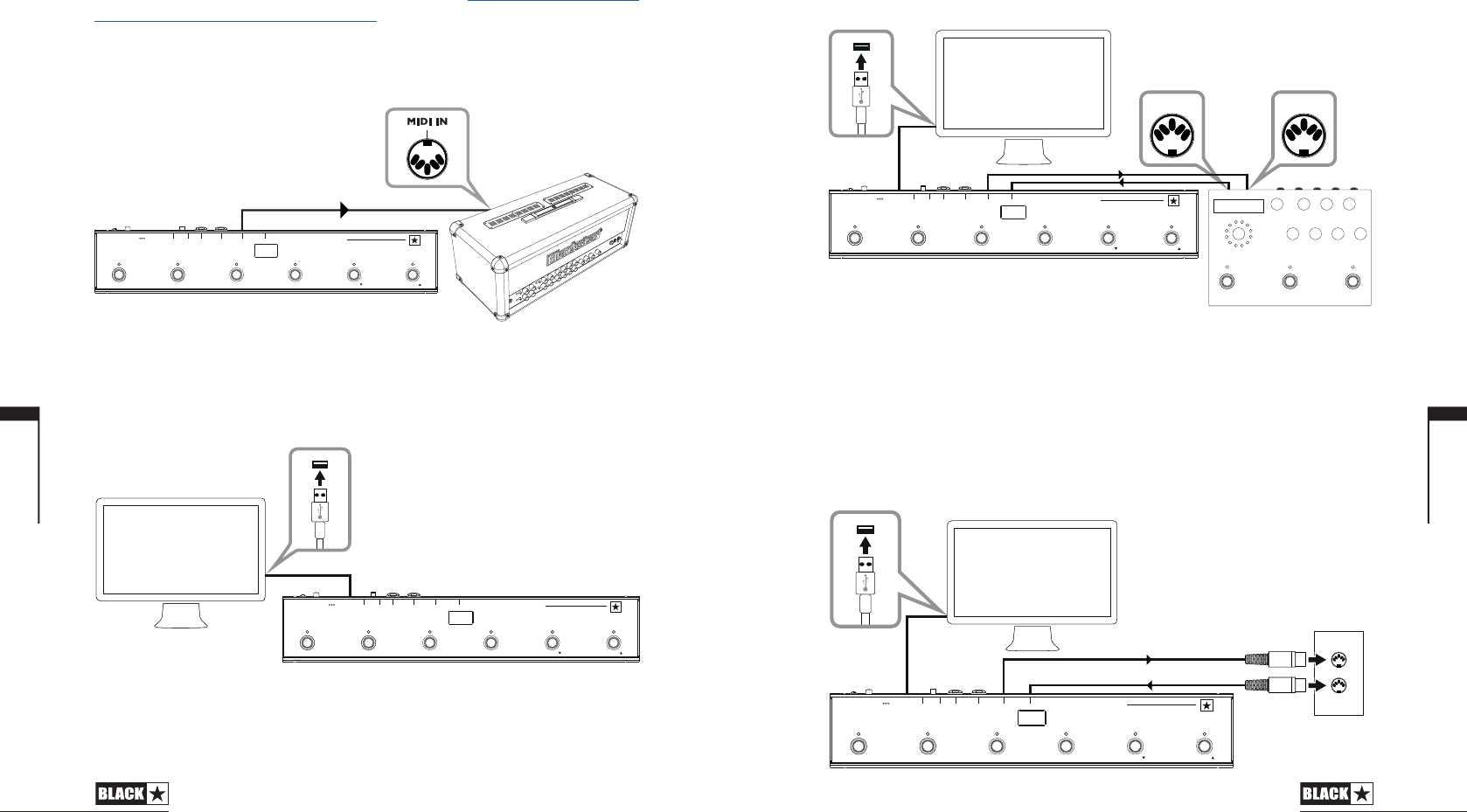
Strymon Nixie control
Live Logic USB PC/MAC
Live Logic MIDI Out Strymon Midi In
Strymon Midi Out Live Logic Midi in
Live Logic Midi Thru set to Off.
MIDI Interface
Live Logic USB PC/MAC
External Midi Hardware MIDI OUT MIDI IN
External Midi Hardware MIDI IN MIDI OUT
Live Logic Midi Thru set to Off
Add Expression pedals to Live Logic to control DAW or external MIDI equipment.
English
11
BA NK BA NK
5 61 2 3 4
PO WER D C9V U SB MOD E
PATC H OU T INCU STO M 2 1
EX P MID I
C U S T O M U S B M I D I C O N T R O L
L I V E L O G I C
BA NK BA NK
5 61 2 3 4
PO WER DC 9V US B MO DE
PATC H OU T INCU STO M 2 1
EX P MI DI
C U S T O M U S B M I D I C O N T R O L
L I V E L O G I C
PC/MAC
USB
MIDI OUT
BA NK B AN K
5 61 2 3 4
PO WE R DC 9V U SB MO DE
PATC H OU T INCU STO M 2 1
EX P MI DI
C U S T O M U S B M I D I C O N T R O L
L I V E L O G I C
PC/MAC
& STRYMON
NIXIE SOFTWARE
STRYMON TIMELINE
USB
MIDI IN
MIDI OUT
MIDI HARDWARE
BA NK BA NK
5 61 2 3 4
PO WE R D C9V US B MO DE
PAT CH O UT INCU STO M 2 1
EX P MI DI
C U S T O M U S B M I D I C O N T R O L
L I V E L O G I C
USB
PC/MAC
MIDI IN
Software
Use your Live Logic MIDI footcontroller with a number of professionally developed
software programs:
Firmware Update
To obtain the latest rmware for your Live Logic Midi Footcontroller, please visit
the Blackstar Live Logic webpage https://www.blackstaramps.com/uk/ranges/live-
logic/usb-midi-controller and download/ install the rmware updater tool, along with
the latest rmware le available. To install the rmware le:
Close any Live Logic Midi Control software.
Open the Firmware updater tool.
Plug in your Live logic via USB.
Load the rmware le.
Click the ‘update’ button.
Note: Monitor and ensure that the progress bar completes to 100%. In the case
that the footswitch fails the rmware update operation, or progress bar stops,
please repeat the upgrade process above.
MODES
ABLETON MODE (For use with Ableton Live Software)
Your Live Logic Midi Footcontroller benets from ocial Ableton Live Integration. In
addition to the standard MIDI mapping functionality, the Ocial integration unlocks
unique looping functionality with up to 6 independent loops.
To enable Ableton Mode on your Live Logic, rst make sure that your Firmware is
up-to-date and you have the latest version of Ableton Live installed.
Select CUSTOM Mode on your Live Logic MIDI Footcontroller using the MODE
SWITCH (6) on the rear panel.
Connect your Live Logic MIDI Footcontroller to your PC or Mac via USB.
English
12
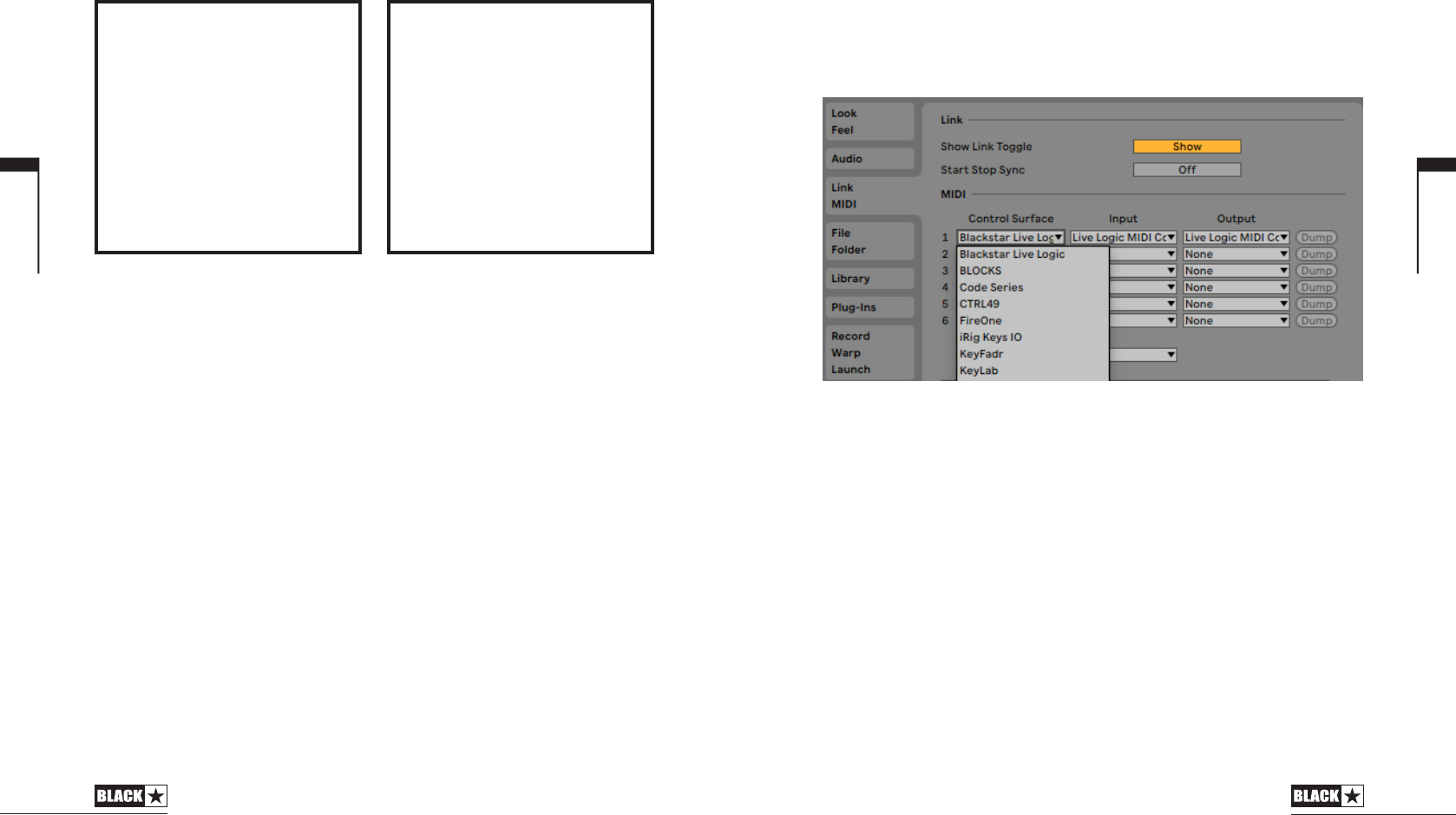
Open Ableton Live
Navigate to the ‘Preferences’ window
Go to the ‘Link MIDI’ tab.
In the ‘Control Surface’ drop down list, select the ‘Blackstar Live Logic’.
Your Live logic MIDI Footcontroller will automatically switch into Ableton Live mode,
and show ‘0’ on the display.
Please refer to the Ableton Live section on page 20 for full functionality.
PATCH MODE
Select PATCH Mode, your Live Logic MIDI Footcontroller using the MODE switch
(6) on the rear panel.
PATCH Mode automatically congures the footswitches to send Program Change
(PC) messages.
In patch mode, the Live logic will send Program Change (PC) messages from 0
to 127.
Switch 1-4 will select the PC number and Switches 5 and 6 will bank down and
up in groups of 4.
When in patch 1, pressing the Bank up (Switch 6) will change the patch to 5.
When in patch 4, pressing the Bank up (Switch 6) will change the patch to 8.
CUSTOM MODE
Select CUSTOM MODE on your Live Logic MIDI Footcontroller using The MODE
switch (6) on the rear panel.
In CUSTOM MODE, The Blackstar Live Logic MIDI Control software can be used
to customise the MIDI messages sent by each of the footswitches and expression
pedals. (See below)
English
13
ABLETON LIVE LITE 10 SOFTWARE
• Blackstar have teamed up with
Ableton Live to create a customised
control surface script and your Live
Logic MIDI Footcontroller includes a free
copy of Ableton’s excellent Live Lite 10
Lite software. You can use all of Live 10
Lite’s essential workflows, instruments
and effects to record songs, create
hands-on with your controller, take
music made in your apps further and
much more.
• Please read the ‘Ableton Mode’
section below for specific information
on this feature.
BLACKSTAR LIVE LOGIC
MIDI CONTROL
• Blackstar Live Logic Midi Control is
a specially designed and developed
software for your Live Logic MIDI
footcontroller software which works on
both PC & Mac.
• Set up and customise the functions
of each footswitch and expression
pedal, save and load your favourite
configuration pre-sets.
• For further information on the functions
and features of the software please read
the relevant sections below.
English
14
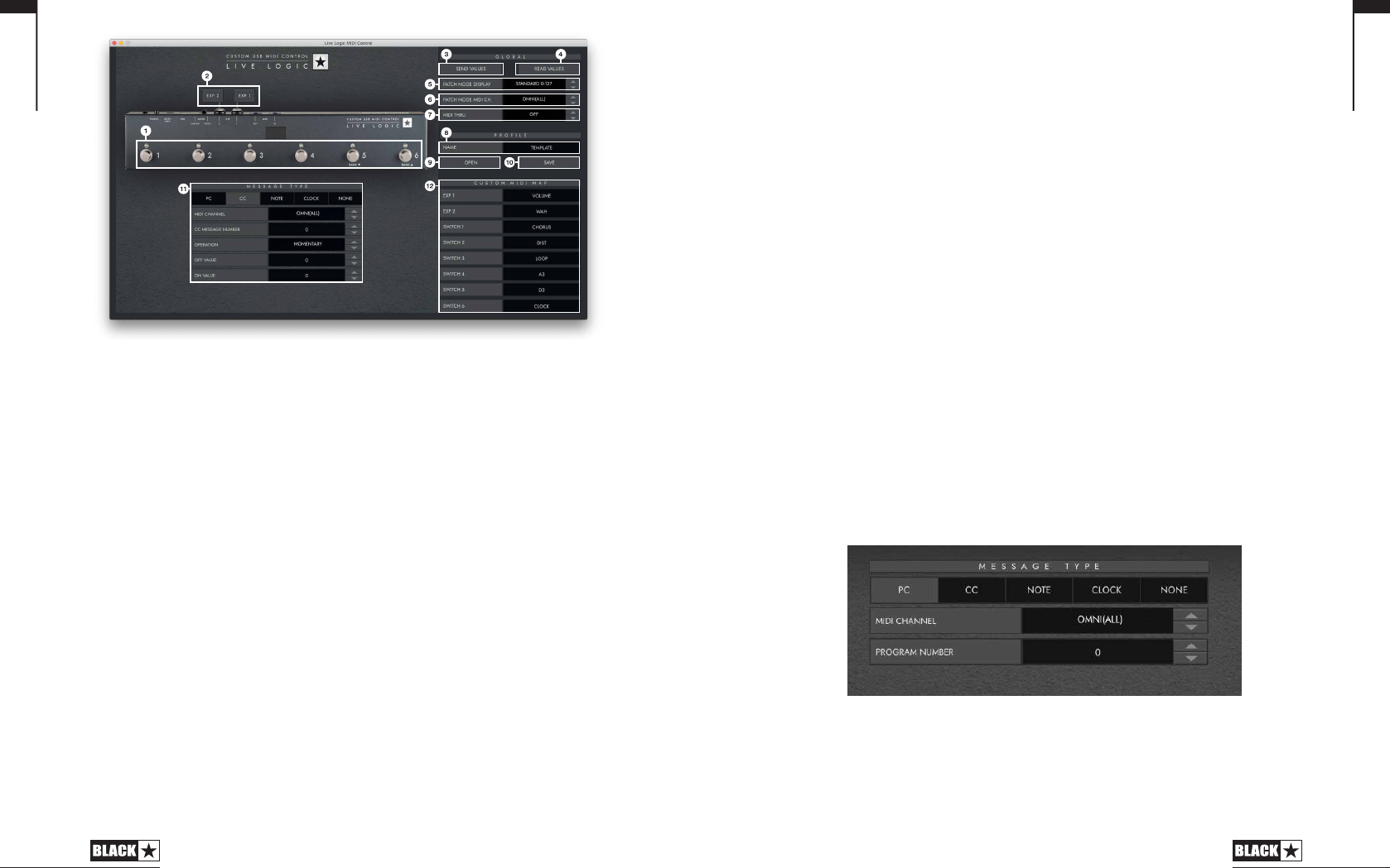
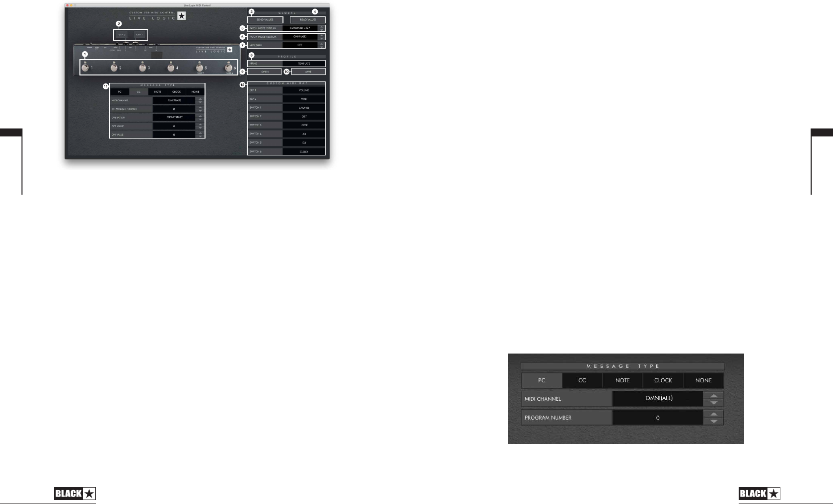
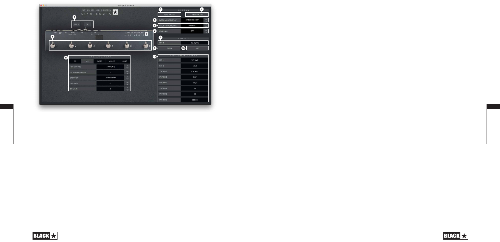
Blackstar Live Logic Midi Control Software
Button Features & Functions
1. FOOTSWITCHES
This displays the footswitch you are currently editing. Press any button on your live
logic while in CUSTOM MODE to select which switch is currently being edited.
2. EXP 1 + EXP 2
Select to edit the Expression pedal settings
3. GLOBAL SEND VALUES
After making any change to the conguration of your Live Logic MIDI Footcontroller,
press the ‘Send Values’ button to conrm and store these settings.
4. GLOBAL READ VALUE
Press ‘Read Values’ when you want to update your App values to what is currently
stored in your Footcontroller. This is done automatically when connecting your
Live Logic. Press this to check that all your settings are stored in your Live Logic
successfully.
5. PATCH MODE DISPLAY
This setting changes the range of the display for the currently active patch.
STANDARD will show 0 for PC message 0, 1 for PC message 1…
OFFSET will show 1 for PC message 0, 2 for PC message 1…
• This can be useful when working with dierent MIDI Hardware that have
patches or pre-sets starting at 1, rather than 0.
6. PATCH MODE MIDI CHANNEL
Select the MIDI channel on which your Live Logic MIDI Footcontroller send Program
Change Messages.
7. MIDI THRU
Selects whether MIDI messages received via MIDI Input are forwarded to the MIDI
Output.
This setting is used when connecting multiple MIDI devices in a chain. For
example, MIDI keyboard output > Live Logic input, Live Logic output > Synth
MIDI input.
Please note: When connecting any loop to the live logic, you should set the
MIDI thru to OFF.
Live Logic Midi out > Pedal MIDI input > Pedal MIDI output > Live Logic MIDI in.
MIDI THRU will default to o.
8. PROFILE NAME
Choose a custom name for your MIDI prole. Each saved prole must have a unique
name.
9. OPEN
Use the ‘Open’ button to load a Prole. Proles are saved as a .bstarmidi le. and
can be shared and loaded on any Live Logic MIDI Footcontroller.
10. SAVE
Once you have customised your prole, save it using this button. Ensure the le
extension is ‘.bstarmidi’.
11. CUSTOM MIDI MAP
Label each individual Footswitch and Expression pedal functions here. These labels
are saved in a prole.
12. MESSAGE TYPE
This section is where you customise the MIDI message for the currently selected
footswitch/ expression pedal. See the section below for further details on each
message type.
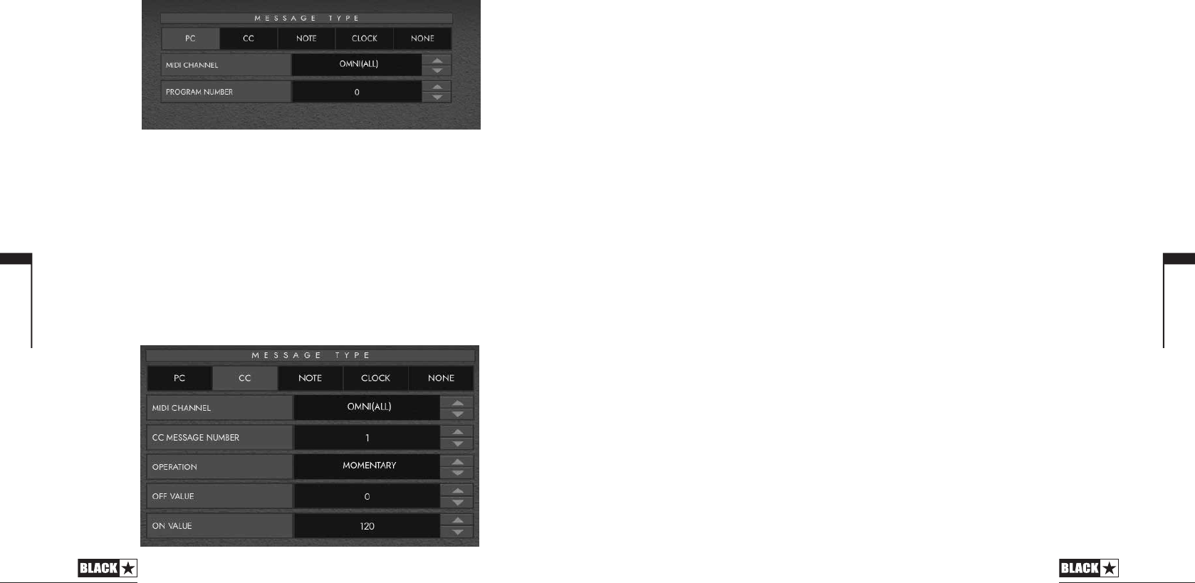
PC – Program Change
• Midi Channel - Set the MIDI Channel on which the selected footswitch/
expression pedal sends the Program Change message.
• This is very useful for rigs that include multiple other pedals or devices being
controlled in a loop by one Live logic MIDI Footcontroller.
• Program Number – Set the Program number that you wish to trigger when
pressing the selected footswitch.
English
15
English
16
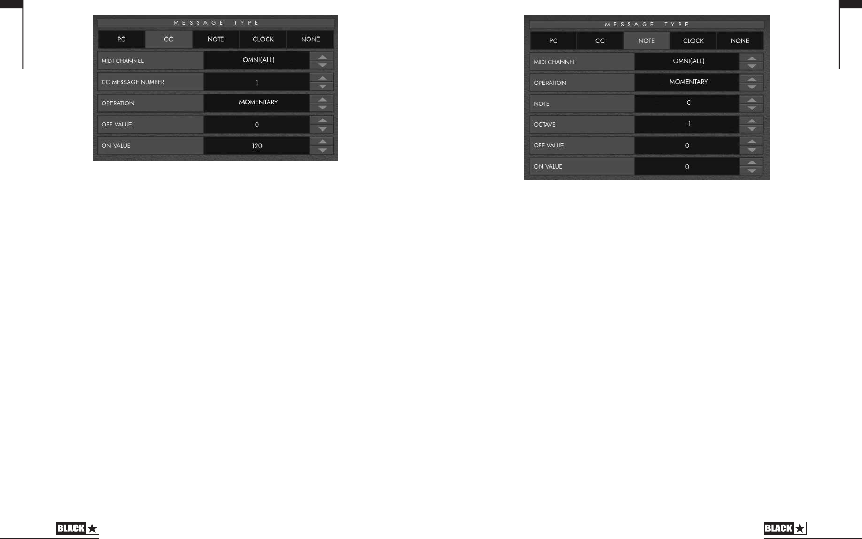
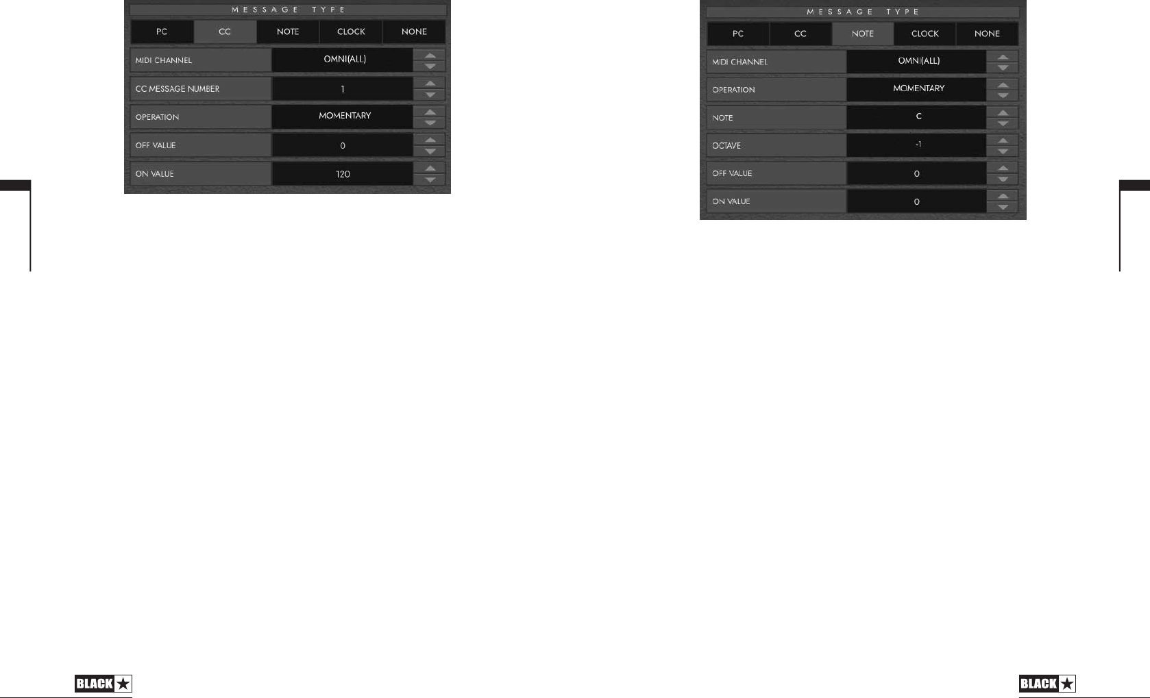
CC - CONTROL CHANGE
MIDI CHANNEL - Set the MIDI Channel on which the selected footswitch/
expression pedal sends the Program Change message.
CC MESSAGE NUMBER - Set the Control Change (CC) number that you wish
to trigger when pressing the selected footswitch or expression pedal. Refer to the
MIDI table in the user manual of the device(s) you wish to control to determine the
function of each CC message. By default, in Custom Mode, the 6 footswitches are
set to CC0 - CC5.
OPERATION - This determines the operation of the 6 footswitches:
• Momentary - Sends the ‘On’ value when the footswitch is pressed and the ‘O’
Value when the footswitch is released. The corresponding LED will be lit whilst
the footswitch is pressed.
• Toggle - Sends the ‘On’ value when pressed once and will stay on until pressed
again. The corresponding LED above the switch will be lit whilst toggled on.
OFF VALUE - Select the data value to send when in the o position. This should
usually be set to 0 for normal use.
ON VALUE - Select what value to be sent when in the o/minimum position. This
should usually be set to 127 for normal use.
EXAMPLE If you want you to use a one button Gain Boost, set the CC number
to control Gain on your Amp/ Plugin, Set the o value to your normal gain level and
the on value to your boosted gain, then set the ‘Operation’ to toggle. This switch
can now be used like a boost pedal.
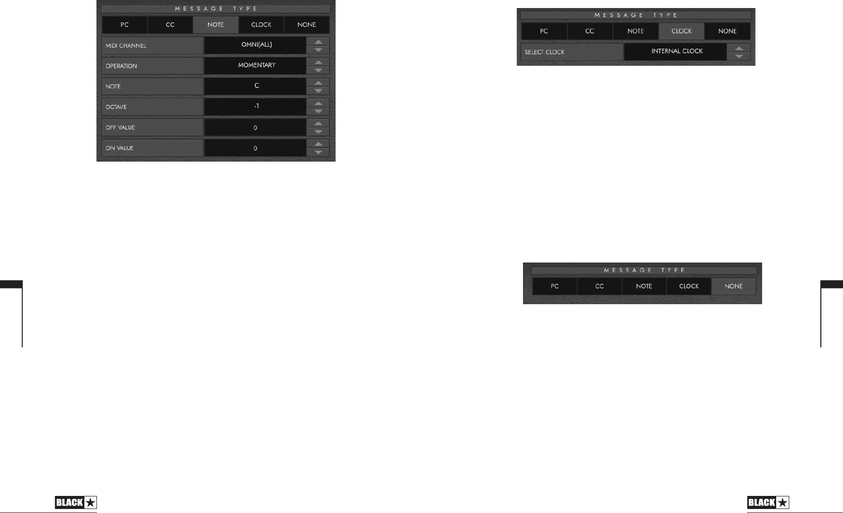
NOTE
MIDI CHANNEL - Set the MIDI Channel on which the selected footswitch/
expression pedal sends the Program Change message.
OPERATION - This determines the operation of the 6 footswitches:
• Momentary - Sends the ‘On’ value when the footswitch is pressed and the ‘O’
Value when the footswitch is released. The corresponding LED will be lit whilst
the footswitch is pressed.
• Toggle - Sends the ‘On’ value when pressed once and will stay on until pressed
again. The corresponding LED above the switch will be lit whilst toggled on.
NOTE - Select which Note to send.
OCTAVE - Select which ‘Octave’ to send the currently selected Note.
OFF VALUE - Select the data value to send when in the o position. This should
usually be set to 0 for normal use.
ON VALUE - Select what value to be sent when in the o/minimum position. This
should usually be set to 127 for normal use.
English
17
19
English
18
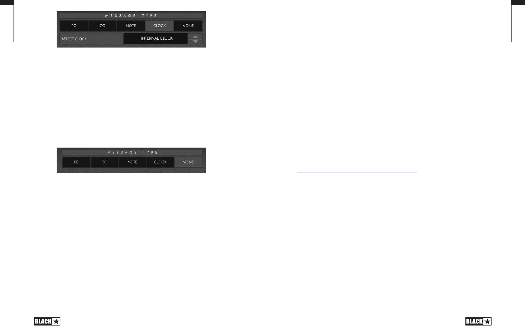
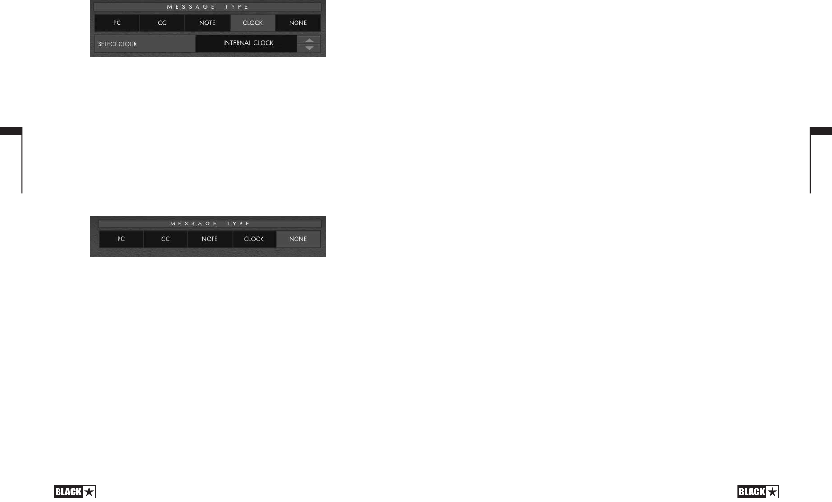
CLOCK
SELECT CLOCK
• INTERNAL CLOCK will use the footswitch selected as a Tap tempo.
- The LED above the footswitch will ash in time with the tempo set.
- Tap the footswitch in time with your desired tempo to set the speed.
- The tempo will be shown on the Live Logic display
• EXTERNAL CLOCK - This will display any incoming clock messages from either the
USB or the MIDI DIN input.
- This is really useful when incorporating a DAW into your live music setup
to act as a visual click track, or for synchronising clocks across all devices.
NONE
If you want to leave a footswitch with no mapping. Select the ‘None’
message type.
Technical Specification
Live Logic MIDI Footcontroller
Powered via either:
9V Battery
USB
External 9V centre-negative PSU
Blackstar PSU-500 (Sold Separately)
Weight (kg): 1.2
Dimensions (mm): 395 x 70 x 35
Accessories:
PSU-500 Power Supply (Sold Separately)
Third party expression pedals (Sold Separately)
REGISTERED TRADEMARKS
Strymon® is a Registered Trademark and division of Damage Control Engineering®, LLC.
PLEASE NOTE:
Foreign language versions of this manual will be available shortly. Please check
back to the handbooks page of our web site regularly or in the meantime contact
our customer services for assistance with your Live Logic MIDI Footcontroller:
https://blackstaramps.com/uk/product-handbooks
Customer services:
https://blackstaramps.com/uk/support
Email: [email protected]
Telephone: +44 (0)1604 817817
English
21
English
20
GETTING STARTED WITH ABLETON
So, you have your new Blackstar Live Logic and you are ready to get set up with
Ableton to utilise its full potential. Let’s get started!
To start with, let us assist you in answering some of the most common questions
we receive in relation to the Live Logic:
What expression pedals work with the Live Logic?
Expression pedals with the TRS wiring layout/polarity should work with the
Live Logic. Expression pedals that only use RTS or TS are not compatible.
Here is a list of common expression pedals and their wiring layout/polarity
http://expressionpedals.com/list-of-expression-pedals
Why aren’t my settings being saved to the pedal when I disconnect the Live
Logic from my computer or turn the Live Logic off?
When you have changed settings in the Live Logic, you need to commit these
changes by clicking “Send Values”. To be sure that these settings have been saved
to the Live Logic, confirm that after clicking “Send Values” there is a pop-up with a
success message.
Why is my Live Logic always set to momentary in Ableton, even if I change
it with the app?
It is likely that the Live Logic is being set to Ableton mode. This is where the Ableton
custom scripts overwrite the current mapping, to enable extra features within
Ableton. For more information on how to configure the different modes when using
Ableton, please see "How do I set the Live Logic up in Ableton mode?" below.
Do I need to complete the Live Logic Firmware update?
Yes, we always advise updating the Live Logic firmware to the latest available
(available via the ALL-DOWNLOADS section of the portal) prior to attempting to
use the Live Logic.
How do I set the Live Logic up in Ableton mode?
To start with you shall need to configure Ableton to ensure it is working correctly
alongside the Live Logic.
You will need to connect the Live Logic via USB and switch it into Custom mode in
order to use the Ableton Live integration.
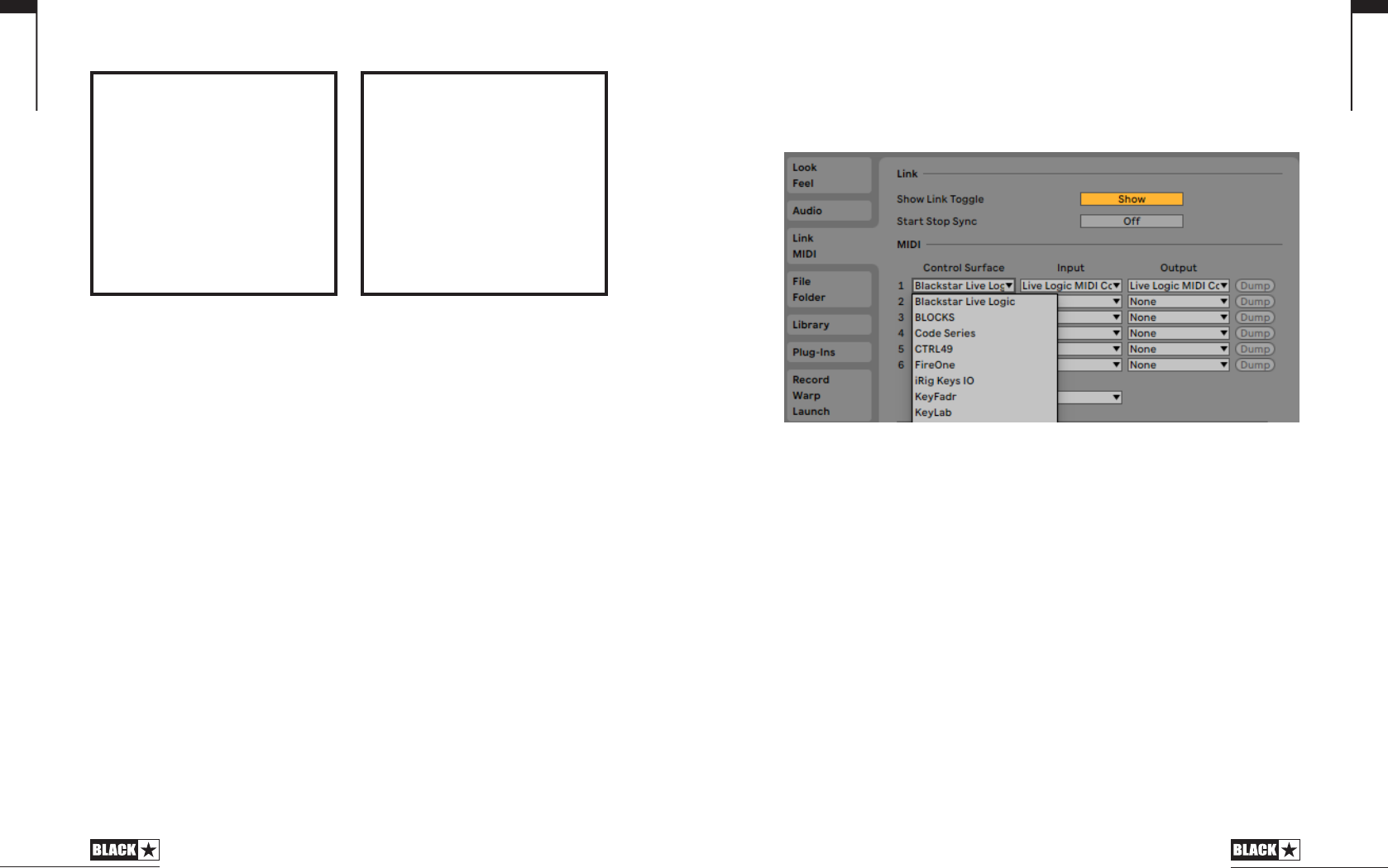
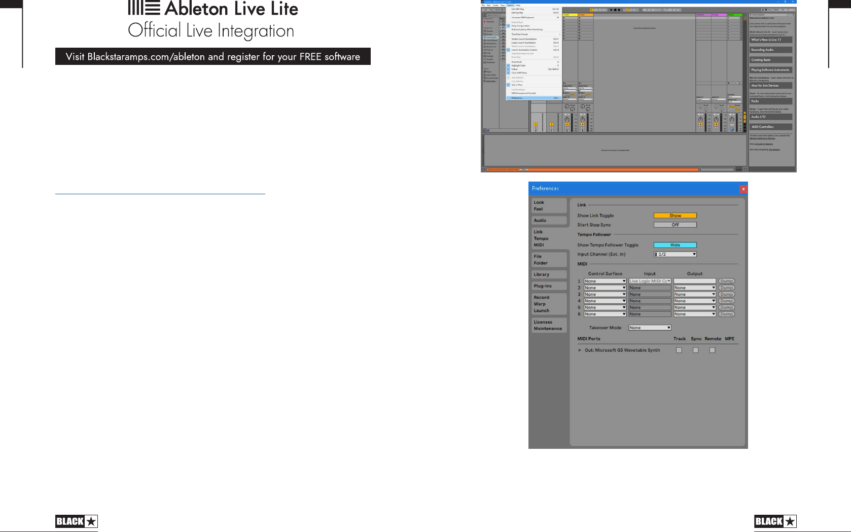
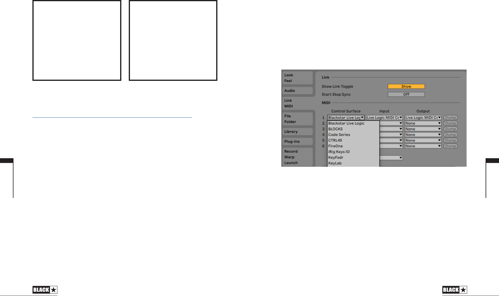
Once this has been completed, you can launch Ableton. Once launched, if you
head to Options, Preferences and finally the Link, Tempo, MIDI option (As pictured
below) a pop-up screen shall appear which shall allow the Live Logic to be set as
your MIDI Control Surface:
Please note that the output can be set to the “Live Logic MIDI Controller”, if
necessary, you will just need to make sure the control surface is set to “None”. If you
wish to use the custom scripts, you will need to set this to the “Blackstar Live Logic”.
English

23
English
22
How do I use the Live Logic when it is in Ableton mode?
We recommend to turn Ableton Live's exclusive arm setting on for use with the Live
Logic. This allows the controller to manage arming automatically and makes for a
more seamless looping experience. More advanced users may want to leave this
setting off and manage arming using other MIDI controllers or Ableton Live itself.
To turn on exclusive arm:
1. Right click any track's arm button
2. Ensure Arm Exclusive is checked
The Live Logic will control the first 6 tracks of your Live set. If you're looping using
an audio input, make sure that the first 6 tracks are audio tracks and that the inputs
are correctly set to the audio input that you want to use. When using exclusive arm,
it's recommended to set the input monitoring mode of your looper tracks to Auto.
You can also add effects to each track so that your loops occupy distinct sonic
spaces. Keep in mind that when starting from scratch, you will be adding layers from
left to right, so your tracks should be ordered accordingly.
Note: The Live Logic will not control tracks that can't be armed, so group tracks
and tracks with no input will be skipped.
If you want to create free, unsynchronized loops, simply set the Global Quantization
setting of Live to None and begin looping.
Otherwise, set the Global Quantization setting to the desired sub division. You can
think of this setting as the minimum length of loops that you will be able to record.
A smaller value allows you to record shorter loops, but requires your timing when
starting and stopping lo ops to be more accurate.
A setting of 1 Bar is a sensible default.
When recording with quantization, it's helpful to also turn the metronome on so that
you always know when loops will be triggered.
When Live is stopped, press and hold any foot switch to start the session.
The Live Logic will display the current beat, indicating that it is ready to start looping.
If you would like to start looping as soon as the session starts, then a quick press of
any switch will start recording a loop on the corresponding track after the count-in
set in Live.
You can also start a session using a pre-recorded backing track. To do so, ensure
the clip containing your backing track is the last clip on one of the first 6 tracks, then
hold the corresponding foot switch to start playing.
In Ableton Live, a loop is represented using a clip. The basic flow of looping with the
Live Logic and Ableton Live is to press a foot switch once to begin recording a clip
on the corresponding track, press it again to stop recording and begin playing, and
then repeat this process for the next loop.
Pressing a foot switch will trigger a clip according to the Global Quantization setting.
For example, pressing the foot switch with a quantization setting of 1 Bar means
recording will start at the beginning of the next bar. When a clip goes from recording
to playing, the next track will be automatically armed so that you can hear your input
signal through the next effects chain before you begin your next loop.
Perfecting your timing: When looping using quantization, be careful to hit the
footswitch well before you want it to be triggered, otherwise you risk making your
loop longer than intended. This can be unintuitive if you're accustomed to analog
loopers that begin looping as soon as your press the switch, but it ensures all of
your loops are perfectly synced.
If you've made a mistake while recording or triggering your loops, you can do a
quick double-tap on the switch for the track that contains the bad loop and it will
be deleted.
In general, double-tapping a switch deletes a clip on the corresponding track
You can stop a loop by holding down the corresponding foot switch and restart it
by holding down the switch again.
Stopping a loop will arm the corresponding track so that you can hear your input
signal and prepare to replace it with a new loop. This allows your session to evolve
over time, and all the results will be saved in Ableton Live so that you can go back
later and arrange them into a song.
Holding down the switch for a track that isn't currently playing will always play the
last stopped clip or the last clip on the track if possible. Otherwise, it will arm the
track.
Using group tracks allows you to stop, start, and delete multiple loops at once,
as well as extend the number of available loop tracks by folding and unfolding the
group track.
Group tracks in Live by selecting the tracks you want to group, right-clicking, and
clicking Group Tracks.
When held, a switch controlling a group track will start or stop all the loop grouped
by the track. Note that this operation will apply to all grouped tracks, not just those
that are currently controllable by the Live Logic. A quick double press will fold or
unfold the group track. Tracks hidden by folding are not controlled by the looper, so
folding a group track allows you to control more than 6 tracks using the Live Logic.
Why isn’t Ableton mode working as expected?
If the controller isn't behaving as expected, try the following:
Ensure the Live Logic is connected to your computer with a working USB cable
and is set to Custom mode via the switch on the back of the controller.
Ensure the "Blackstar Live Logic" control surface is selected in Ableton
Live's MIDI Preferences and that MIDI inputs and outputs are set to "Live Logic
MIDI Controller".
English

2524
All electrical and electronic products should be disposed of separately
from the municipal waste stream via designated collection facilities
appointed by the government or the local authorities.
Français
Français
Cet appareil doit être utilisé dans un environnement bien ventilé et ne doit jamais être
mis sous tension si l'endroit est conné.

Caractéristiques
Le pédalier MIDI USB Live Logic de Blackstar est le résultat d'innombrables heures
de recherche technique et d'analyse comparative avec les produits leaders du
marché. Conçu dès le départ pour les musiciens et les producteurs, il regorge de
fonctionnalités malgré sa taille compacte.
Le pédalier MIDI USB Live Logic vous permet de contrôler rapidement et facilement
tout matériel ou plateforme logicielle MIDI, ainsi que des plugins. Envoyez de
manière transparente des messages de changement de programme et affectez
les commandes de paramètres à n’importe lequel des switches, ou assignez la
commande en continu de tout paramètre MIDI à une pédale d'expression grâce
aux deux entrées pour pédale d'expression (pédale d'expression non fournie). Le
MIDI par USB est également inclus pour l’utilisation avec des stations de travail
audio numériques, plugins et logiciels de séquençage/échantillonnage live comme
Ableton Live™.
Ce produit est fourni avec une copie gratuitement téléchargeable du puissant
logiciel Live 10 Lite d'Ableton. Même s’il s’agit d'un excellent logiciel, vous avez
toute liberté d'utiliser et de contrôler divers produits MIDI avec votre propre logiciel
de prédilection.
Alimentez votre pédalier MIDI USB Live Logic où que vous soyez, par USB, pile 9 V
ou alimentation secteur.
27
Introduction
Merci d'avoir acheté ce pédalier MIDI USB Blackstar Live Logic.
Comme tous nos produits, le pédalier Live Logic est le résultat d'innombrables
heures de recherche et de développement minutieux par notre équipe de conception
de réputation mondiale. Basée à Northampton (R-U), l'équipe Blackstar est
composée de musiciens chevronnés dont le seul but est de fournir aux musiciens
et producteurs des outils ultimes pour leur propre expression.
Tous les produits Blackstar sont soumis à des tests complets en laboratoire et en
conditions réelles pour s’affranchir véritablement de tout compromis en termes de
fiabilité, de qualité et avant tout de SON.
Veuillez lire attentivement la totalité de ce mode d'emploi pour vous garantir de
profiter au maximum de votre nouveau produit Blackstar.
Si vous aimez ce que vous entendez et désirez en savoir plus sur la gamme des
produits Blackstar, visitez notre site web à l'adresse www.blackstaramps.com.
Merci !
L'équipe Blackstar
26
Français
Français
La plage de programmes (0-127/1-128) peut se sélectionner dans le logiciel
de contrôle par USB.
Switches 1 - 4 : envoient le message de changement de programme
correspondant, par banques de 4.
Switch 5 : banque inférieure.
Switch 6 : banque supérieure.
Basculer le sélecteur sur la droite (« CUSTOM ») vous permet d’utiliser le logiciel
Blackstar Live Logic MIDI Control par USB afin de personnaliser les messages MIDI
envoyés au travers du câble MIDI et de l'USB. Affectez n’importe lesquels des types
de messages suivants aux six switches :
Changement de programme
Changement de commande
Note
Horloge
Aucun
7 & 8. Le pédalier Live Logic peut être alimenté par USB depuis votre PC/Mac, par
une pile 9 V appropriée ou par l’adaptateur secteur compact PSU-500 Blackstar
(vendu séparément) qui fonctionne sur CA 100-240 V et est fourni avec 4 types de
broches différents afin de pouvoir l’utiliser dans de nombreux pays de par le monde.
9. Enclencher l’interrupteur d’alimentation met l’unité sous tension, ce qui allume
l’afficheur à LED de la façade. Appuyer à nouveau sur l’interrupteur pour le faire
ressortir éteint immédiatement le pédalier Live Logic.
Exemples de configuration correcte avec des produits
spécifiques
Blackstar Silverline
Sortie MIDI du Live Logic ---> entrée MIDI du Silverline
Mode PATCH – pour changer le patch sur votre Silverline (régler l'affichage de
mode de patch sur OFFSET)
Mode CUSTOM ---> télécharger le modèle Silverline depuis
https://www.blackstaramps.com/uk/ranges/live-logic/usb-midi-controller pour
un exemple d’assignation MIDI.
29
Boutons Et Fonctionnalités Du Live Logic
Face Avant (en mode Patch)
1. 6 switches indépendants avec leur propre LED qui vous indiquent le switch
actuellement sélectionné une fois que vous avez appuyé dessus.
2. Le « switch 5 » donne accès à la « banque inférieure » et le « switch 6 » à la
« banque supérieure ».
3. Afficheur à LED de façade bien lisible sur scène. Une fois l'unité sous tension,
l'afficheur à LED s'allume.
Face Arrière
4. 2 prises MIDI (entrée/sortie) vous permettent de connecter du matériel MIDI au
moyen de câbles DIN 5 broches standard.
5. Deux entrées pour des pédales d'expression individuelles vous permettent de
connecter deux pédales à la fois. Celles-ci peuvent être programmées au moyen
du logiciel de contrôle par USB.
6. Le sélecteur MODE permet de choisir entre le mode « PATCH » et le mode
« CUSTOM » (personnalisé).
Basculer le sélecteur MODE sur la gauche (« PATCH ») vous permet d’envoyer des
messages de changement de programme à tout appareil MIDI connecté par câble
MIDI ou USB.
28
BA N K BA N K
5 61 2 3 4
P OW ER D C9V U SB M ODE
PAT CH OU T I NCU ST OM 2 1
E XP M IDI
C U S T O M U S B M I D I C O N T R O L
L I V E L O G I C
BA NK BA NK
5 61 2 3 4
PO WE R DC 9V U SB MO DE
PAT CH OU T I NCU STO M 2 1
EX P MI DI
C U S T O M U S B M I D I C O N T R O L
L I V E L O G I C
BA NK BA NK
5 61 2 3 4
PO WER D C9 V USB MO DE
PATC H OU T INCU STO M 2 1
EX P MI DI
C U S T O M U S B M I D I C O N T R O L
L I V E L O G I C
Français
Français
Blackstar Series One
Sortie MIDI du Live Logic ---> entrée MIDI du Series One
Mode PATCH – pour changer le canal sur votre Series One (régler l'affichage
de mode de patch sur OFFSET)
Mode CUSTOM ---> télécharger le modèle Series One depuis
https://www.blackstaramps.com/uk/ranges/live-logic/usb-midi-controller pour
changer de patch avec deux switches laissés inaffectés pour un autre
équipement MIDI.
Contrôle de plugin de station de travail audio numérique (DAW ou STAN)
USB du Live Logic ---> PC/MAC
30
Contrôle de Strymon Nixie
USB du Live Logic ---> PC/MAC
Sortie MIDI du Live Logic ---> entrée MIDI du Strymon
Sortie MIDI du Strymon ---> entrée MIDI du Live Logic
Renvoi MIDI THRU de Live Logic réglé sur Off
Interface MIDI
USB du Live Logic ---> PC/MAC
Sortie MIDI de matériel MIDI externe ---> entrée MIDI
Entrée MIDI de matériel MIDI externe ---> sortie MIDI
Renvoi MIDI THRU de Live Logic réglé sur Off
Ajoutez des pédales d'expression au Live Logic pour contrôler une DAW
ou du matériel externe.
31
BA NK BA NK
5 61 2 3 4
PO WER D C9V U SB MOD E
PATC H OU T INCU STO M 2 1
EX P MID I
C U S T O M U S B M I D I C O N T R O L
L I V E L O G I C
BA NK BA NK
5 61 2 3 4
PO WER DC 9V US B MO DE
PATC H OU T INCU STO M 2 1
EX P MI DI
C U S T O M U S B M I D I C O N T R O L
L I V E L O G I C
PC/MAC
USB
MIDI OUT
BA NK B AN K
5 61 2 3 4
PO WE R DC 9V U SB MO DE
PATC H OU T INCU STO M 2 1
EX P MI DI
C U S T O M U S B M I D I C O N T R O L
L I V E L O G I C
PC/MAC
& STRYMON
NIXIE SOFTWARE
STRYMON TIMELINE
USB
MIDI IN
MIDI OUT
MIDI HARDWARE
BA NK BA NK
5 61 2 3 4
PO WE R D C9V US B MO DE
PAT CH O UT INCU STO M 2 1
EX P MI DI
C U S T O M U S B M I D I C O N T R O L
L I V E L O G I C
USB
PC/MAC
MIDI IN
Français
Français
LOGICIELS
Utilisez votre pédalier MIDI Live Logic avec de nombreux logiciels développés par
des professionnels:
MISE À JOUR DU LOGICIEL
Pour obtenir le tout dernier rmware (logiciel interne) de votre pédalier MIDI Live Logic,
veuillez consulter la page web Blackstar Live Logic https://www.blackstaramps.
com/uk/ranges/live-logic/usb-midi-controller et télécharger/installer l'outil de mise
à jour du rmware, ainsi que le chier de rmware le plus récent qui soit disponible.
Pour installer le chier du rmware :
Fermez tout logiciel Live Logic MIDI Control.
Ouvrez l'outil de mise à jour du firmware.
Branchez votre Live Logic par USB.
Chargez le fichier du firmware.
Cliquez sur le bouton « Update » (mettre à jour).
Note : surveillez la barre de progression et assurez-vous qu’elle arrive bien à
100 %. En cas d'échec de l'opération de mise à jour du firmware ou d'arrêt de
la barre de progression, veuillez répéter le processus de mise à jour ci-dessus.
MODES
ABLETON MODE (pour l'utilisation avec le logiciel Ableton Live)
Votre pédalier MIDI Live Logic bénécie de l'intégration ocielle d'Ableton Live. En
plus de la fonctionnalité d’assignation MIDI standard, l'intégration ocielle libère une
fonctionnalité de bouclage unique avec jusqu'à 6 boucles indépendantes.
Pour activer le mode Ableton sur votre Live Logic, assurez-vous d'abord que votre
rmware est à jour et que vous avez bien la dernière version d'Ableton Live installée..
Sélectionnez le mode CUSTOM sur votre pédalier MIDI Live Logic au moyen du
sélecteur MODE (6) de la face arrière.
32
Connectez votre pédalier MIDI Live Logic à votre PC ou Mac par USB.
Ouvrez Ableton Live.
Accédez à la fenêtre « Préférences ».
Ouvrez l'onglet « Link MIDI ».
Dans la liste déroulante « Surface de contrôle », sélectionnez « Blackstar Live
Logic ».
Votre pédalier MIDI Live Logic basculera automatiquement en mode Ableton Live,
et indiquera « 0 » dans l’acheur.
Veuillez vous référer à la section Ableton Live ci-dessous pour connaître toutes les
fonctionnalités.
MODE PATCH
Sélectionnez le mode PATCH sur votre pédalier MIDI Live Logic à l’aide du
sélecteur MODE (6) de la face arrière.
Le mode PATCH configure automatiquement les switches pour envoyer des
messages de changement de programme.
En mode PATCH, le Live Logic envoie les messages de changement de
programme 0 à 127.
Les switches 1-4 sélectionnent le numéro de changement de programme et les
switches 5 et 6 font respectivement passer à la banque inférieure et supérieure
par groupes de 4.
En patch 1, presser le switch 6 (banque supérieure) fait passer au patch 5.
En patch 4, presser le switch 6 (banque supérieure) fait passer au patch 8.
MODE CUSTOM
Sélectionnez le mode CUSTOM sur votre pédalier MIDI Live Logic au moyen
du sélecteur MODE (6) de la face arrière.
En mode CUSTOM, le logiciel Blackstar Live Logic MIDI Control permet
de personnaliser les messages MIDI envoyés par chacun des switches et des
pédales d’expression (voir ci-dessous)
33
LOGICIEL ABLETON LIVE 10 LITE
• Blackstar have teamed up with
Ab• Blackstar s'est associé à
Ableton Live pour créer un script de
surface de contrôle personnalisé et votre
pédalier MIDI Live Logic est fourni avec
une copie gratuite de l'excellent logiciel
Live 10 Lite d'Ableton. Vous pouvez
utiliser tous les flux de travail, instruments
et effets essentiels de Live 10 Lite pour
enregistrer des morceaux, créer de façon
pratique avec votre contrôleur, pousser
plus loin la musique produite dans vos
applications et bien plus encore.
• Veuillez lire la section « Mode Ableton »
ci-dessous pour des informations
spécifiques sur cette fonctionnalité.
BLACKSTAR LIVE LOGIC MIDI
CONTROL
• Blackstar Live Logic MIDI Control est un
logiciel spécialement conçu et développé
pour votre pédalier MIDI Live Logic et
qui fonctionne à la fois sur PC et Mac.
• Configurez et personnalisez les
fonctions de chaque switch et pédale
d'expression, sauvegardez et rechargez
vos configurations préréglées préférées
• Pour plus d'informations sur les
fonctions et caractéristiques du logiciel,
veuillez lire les sections correspondantes
ci-dessous.
Français
Français
34
Logiciel Blackstar Live Logic Midi Control
Caractéristiques Et Fonctions Des Boutons
1. SWITCHES
Indiquent le switch que vous modiez actuellement. Appuyez sur le switch à modier
sur votre Live Logic en mode CUSTOM. .
2. EXP 1 + EXP 2
Sélectionnez-les pour modier les réglages des pédales d'expression.
3. GLOBAL SEND VALUES
Après avoir modié la conguration de votre pédalier MIDI Live Logic, pressez le
bouton « Send Values » (lui envoyer les valeurs) pour conrmer et mémoriser ces
réglages.
4. GLOBAL READ VALUE
Pressez « Read Values » (lire ses valeurs) quand vous souhaitez remplacer les
valeurs de votre appli par celles actuellement mémorisées dans votre pédalier. Cela
se fait automatiquement lors de la connexion de votre Live Logic. Pressez ce bouton
pour vérier que tous vos réglages sont bien enregistrés dans votre Live Logic.
5. PATCH MODE DISPLAY
Ce réglage change la plage d'achage pour le patch actuellement actif..
STANDARD achera 0 pour le message de changement de programme 0, 1
pour le message de changement de programme 1……
OFFSET achera 1 pour le message de changement de programme 0, 2 pour
le message de changement de programme 1…
• Cela peut être utile lorsque vous travaillez avec diérents équipements
MIDI dont les patches ou presets peuvent être numérotés à partir de 1 plutôt
que de 0.
6. PATCH MODE MIDI CH.
Sélectionnez ici le canal MIDI sur lequel votre pédalier MIDI Live Logic enverra les
messages de changement de programme.
7. MIDI THRU
Détermine si les messages MIDI reçus par l'entrée MIDI sont renvoyés par la sortie
MIDI.
Ce réglage s’utilise lorsque plusieurs appareils MIDI sont enchaînés en guirlande.
Par exemple, sortie d’un clavier MIDI > entrée de Live Logic, sortie de Live Logic
> entrée d’un synthé MIDI.
À noter : en cas de connexion en boucle avec le Live Logic, vous devez régler
MIDI THRU sur OFF.
Sortie MIDI du Live Logic > entrée MIDI de pédale > sortie MIDI de pédale >
entrée MIDI du Live Logic.
MIDI THRU sera par défaut sur OFF.
8. PROFILE NAME
Choisissez un nom personnalisé pour votre prol MIDI. Chaque prol sauvegardé
doit avoir un nom qui lui est propre.
9. OPEN
Utilisez le bouton « OPEN » (ouvrir) pour charger un prol. Les prols sont enregistrés
sous forme de chiers .bstarmidi et peuvent être partagés et chargés par n'importe
quel pédalier MIDI Live Logic.
10. SAVE
Une fois que vous avez personnalisé votre prol, sauvegardez-le à l'aide de ce
bouton. Assurez-vous que l'extension du chier est bien « .bstarmidi ».
11. CUSTOM MIDI MAP
Indiquez ici les fonctions propres à chaque switch et à chaque pédale d'expression.
Ces intitulés sont sauvegardés dans un prol.
12. MESSAGE TYPE
Cette section vous permet de personnaliser le message MIDI pour le switch/pédale
d'expression actuellement sélectionné. Voir la section ci-dessous pour plus de
détails sur chaque type de message.
PC – Changement de programme
• Midi Channel - Choisissez ici le canal MIDI sur lequel le switch/pédale
d'expression sélectionné envoie le message de changement de programme..
• C'est très utile pour les congurations comportant plusieurs autres pédales ou
appareils contrôlés dans une boucle par un même pédalier MIDI Live Logic
• Program Number – Choisissez ici le numéro de programme que vous
souhaitez envoyer en pressant le switch sélectionné.
35
Français
Français
36
CC – CHANGEMENT DE COMMANDE
MIDI CHANNEL - Choisissez ici le canal MIDI sur lequel le switch/pédale
d'expression sélectionné envoie le message de changement de commande.
CC MESSAGE NUMBER - Choisissez ici le numéro de contrôleur (changement
de commande ou CC) que vous souhaitez régler par pression sur le switch ou
la pédale d'expression sélectionné. Consultez le tableau MIDI du mode d’emploi
du ou des appareils que vous souhaitez contrôler pour déterminer la fonction de
chaque message CC. Par défaut, en mode CUSTOM, les 6 switches sont réglés
pour envoyer les CC0 à CC5.
OPERATION - Détermine le fonctionnement des 6 switches :
• Momentary - Envoie la valeur « On » quand le switch est pressé et
« O » quand il est relâché. La LED correspondante s'allume tant que le switch
est pressé.
• Toggle - Envoie la valeur « On » quand on appuie une fois sur le switch, et
la maintient jusqu’à la prochaine pression. La LED correspondante au-dessus du
switch est allumée tant que la valeur est sur « On ».
OFF VALUE - Sélectionnez ici la valeur envoyée en position O. En usage
normal, elle est habituellement égale à 0.
ON VALUE - Sélectionnez ici la valeur envoyée en position On/maximale. En
usage normal, elle est habituellement égale à 127.
EXAMPLE: Si vous souhaitez utiliser un bouton pour augmenter le gain, réglez
le numéro de CC pour contrôler le gain sur votre ampli/plugin, réglez la valeur
O sur votre niveau de gain normal et la valeur On sur votre gain augmenté, puis
réglez « OPERATION » sur Toggle. Ce switch peut maintenant être utilisé comme
une pédale Boost.
NOTE
MIDI CHANNEL - Choisissez ici le canal MIDI sur lequel le switch/pédale
d'expression sélectionné envoie le message de note.
OPERATION - Détermine le fonctionnement des 6 switches :
• Momentary - Envoie la valeur « On » quand le switch est pressé et
« O » quand il est relâché. La LED correspondante s'allume tant que le
switch est pressé.
• Toggle - Envoie la valeur « On » quand on appuie une fois sur le switch et
la maintient jusqu’à la prochaine pression. La LED correspondante au-dessus
du switch est allumée tant que la valeur est sur « On ».
NOTE - Sélectionnez ici la note à envoyer.
OCTAVE - Sélectionnez ici l’octave de la note à envoyer.
OFF VALUE - Sélectionnez ici la valeur envoyée en position O. En usage
normal, elle est habituellement égale à 0.
ON VALUE - Sélectionnez ici la valeur envoyée en position On/maximale. En
usage normal, elle est habituellement égale à 127.
37
Français
Français
3938
CLOCK
SELECT CLOCK
• INTERNAL CLOCK (horloge interne) fera appel au switch sélectionné pour
battre le tempo.
- La LED au-dessus du switch clignotera en mesure avec le tempo xé.
- Battez le tempo désiré sur le switch pour xer la vitesse.
- Le tempo sera indiqué dans l’acheur du Live Logic.
• EXTERNAL CLOCK - Ache tout message d'horloge reçu par l’entrée USB
ou MIDI DIN.
- C'est très utile pour intégrer une station de travail audio numérique à votre
conguration de jeu live an d’avoir une piste de clic visuelle ou pour synchroniser
les horloges de tous les appareils.
NONE
Si vous souhaitez laisser un switch non affecté, sélectionnez le type de
message « None ».
Caractéristiques Techniques
Pédalier MIDI Live Logic
Alimenté par au choix :
Pile 9V
USB
Adaptateur externe 9 V avec le moins au centre
PSU-500 Blackstar (vendu séparément)
Poids (kg): 1.2
Dimensions (mm): 395 x 70 x 35
Accessories:
Adaptateur externe PSU-500 (vendu séparément)
Pédales d'expression tierces (vendues séparément)
REGISTERED TRADEMARKS
Strymon® est une marque déposée et une division de Damage Control Engineering®, LLC.
Français
Français
4140
Japanese
Japanese
4342
All electrical and electronic products should be disposed of separately
from the municipal waste stream via designated collection facilities
appointed by the government or the local authorities.
Japanese
Japanese
主な特徴
本機はBlackstarチームの膨大な研究のもとに開発されました。ミュージシャンとプロ
デューサーのためにゼロから設計された、コンパクトで機能満載のUSB MIDIフットコ
ントローラーです。
Live Logic MIDIフットコントローラーは、あらゆるMIDIハードウェアやソフトウェア、
プラグインのパフォーマンス・コントロールをクイックかつ簡単に行なえます。プログラ
ム・チェンジ・メッセージやマップ・パラメーター・コントロールをスイッチに送 信した
り、2系統のエクスプレッション・ペダル端子を使用してMIDIパラメーターの連続的な
コントロールをペダルで 行うことができます(エクスプレッション・ペダルは 別 売りで
す)。DAWやプラグイン、Ableton Live™などのライブ・シーケンサー/サンプリング・
ソフトウェアのコントロールが行えるMIDI-USB機能も搭載しています。
本機をお買い上げいただくと、Ableton Live 10 Liteを無償でダウンロードできます。
もちろんお客様がお使いのソフトウェアで一連のMIDI機器を自由にコントロールする
こともできます。
電源はUSBバスパワー、9V電池、一般的なパワー・サプライに対応。あらゆるシチュエ
ーションで使 用できます。
はじめに
この度はBlackstar Live Logic USB MIDIコントローラーをお買い上げいただき、誠に
ありがとうございます。
他のBlackstar製品と同様、本機もワールドクラスの開発チームにより膨大な時間をかけ
て研究開発した成果です。イギリス・ノーザンプトンを拠点とするBlackstarは、すべてのス
タッフが現役ミュージシャンであり、各製品の開発プロセスは、ミュージシャンが自分の音
を表現することができるための究極のツールづくりをゴールとしています。
すべてのBlackstar製品は実験室、そして現場での過酷なテストを受け、信頼性や品質
面、そして何よりその サウンドが確かなものである点で一切の妥協をしておりません。
本機を気に入ってくださり、さらに他のBlackstar製品にご興味がありましたら、ぜひ
Blackstarウェブサイ ト(www.blacktaramps.com)にアクセスしてみてください。
重ねて、この度はBlackstar製品をお買い上げいただき、誠にありがとうございました。
Blackstarチーム
4544
Japanese
プログラム・チェンジのタイプ(0-127/1-128)は、USBコントロール・
ソフトウェア上で設定できます。
フットスイッチ1-4:選択したバンク内でのプログラム・チェンジ・メッセ
ージを送信します。
フットスイッチ5:バンク・ダウン
フットスイッチ6:バンク・アップ
カスタム・モード(右側)を選択:USBコントロール・ソフトウェアを使用
して、送信するMIDIメッセージをカスタマイズできます。以下のメッセージ・
タイプを6つのフットスイッチに自由にマッピングできます。
プログラム・チェンジ
コントロール・チェンジ
ノート
クロック
なし
7 & 8. 電源はUSBバスパワー、9V電池、外部DC9Vパワー・サプライ
(センターマイナス)に対応しています。別売りオプションのPSU-500は
AC100-240Vに対応。4タイプの変換プラグを付属し、世界中で使用できます。
9. 電源ボタン。オンにすると中央のLEDディスプレイが光ります。
接続例
Blackstar Silverline
Live Logic のMIDI出力 → Silverline MIDI入力
パッチ・モード:Silverlineのパッチを変更します。
(パッチ・モードの表示をオフセットに設定します)
カスタム・モード:MIDIマッピングの一例はBlackstarウェブサイ
トよりSilverlineテンプレートをダウンロードしてください。
https://www.blackstaramps.com/uk/ranges/live-logic/usb-midi-controller
各部の特徴
フロントパネル(パッチ・モード時)
1. 6つの独立したスイッチ。
各スイッチにはLEDが付いており設定がひと目で分かります。
2. スイッチ5でバンク・アップ、スイッチ6でバンク・ダウンします。
3. ステージ上でも確認しやすいLEDディスプレイを装備。
選択したプログラム・ナンバーを表示します。
リアパネル
4. MIDI IN/OUT端子を装備。
一般的な5ピンタイプのMIDIケーブルをご使用ください。
5. 2系統の独立したエクスプレッション・ペダル端子を装備し、
それぞれパラメーターのコントロールが可能です。
6. 2つのモード(パッチ/カスタム)を切り替えるモード・セレクト・スイッチです。
パッチ・モード(左側)を選択:MIDIまたはUSBケーブルで接続したMIDI機器
にプログラム・チェンジ(PC)メッセージを送信します。
Japanese
BA N K BA N K
5 61 2 3 4
P OW ER D C9V U SB M ODE
PAT CH OU T I NCU ST OM 2 1
E XP M IDI
C U S T O M U S B M I D I C O N T R O L
L I V E L O G I C
BA NK BA NK
5 61 2 3 4
PO WE R DC 9V U SB MO DE
PAT CH OU T I NCU STO M 2 1
EX P MI DI
C U S T O M U S B M I D I C O N T R O L
L I V E L O G I C
BA NK BA NK
5 61 2 3 4
PO WER D C9 V USB MO DE
PATC H OU T INCU STO M 2 1
EX P MI DI
C U S T O M U S B M I D I C O N T R O L
L I V E L O G I C
4746
Japanese
Japanese
Strymon Nixie control
Live LogicのUSB端子 → PC/Mac
Live Logicの MIDI出力 → Strymon MIDI入力
Strymon MIDI出力 → Live LogicのMIDI入力
本機のMIDIスルー機能はオフに設定されています。
MIDI インターフェイス
Live LogicのUSB端子 → PC/Mac
外部MIDIハードウェアのMIDI出力 → MIDI入力
外部MIDIハードウェアのMIDI入力 → MIDI出力
本機のMIDIスルー機能はオフに設定されています。
Live Logicにエクスプレッションペダルを接続し、DAWや外部MIDI機器を
コントロールすることも可能です。
Blackstar Series One
Live LogicのMIDI出力 → Series One MIDI入力
パッチ・モード:Series Oneのチャンネルを変更します。
(パッチ・モードの表 示をオフセットに設定します)
カスタム・モード:Blackstarウェブサイト
( https://www.blackstaramps.
com/uk/ranges/live-logic/usb-midi-controller )よ り S e r i e s O n e テ ン プ レ ー ト を
ダウンロードし、他のMIDI機器用に2つのスイッチを空白のままにしてパッチ
を変更します。
DAWプラグイン・コントロール
Live LogicのUSB端子 → PC/Mac
BA NK BA NK
5 61 2 3 4
PO WER D C9V U SB MOD E
PATC H OU T INCU STO M 2 1
EX P MID I
C U S T O M U S B M I D I C O N T R O L
L I V E L O G I C
BA NK BA NK
5 61 2 3 4
PO WER DC 9V US B MO DE
PATC H OU T INCU STO M 2 1
EX P MI DI
C U S T O M U S B M I D I C O N T R O L
L I V E L O G I C
PC/MAC
USB
MIDI OUT
BA NK B AN K
5 61 2 3 4
PO WE R DC 9V U SB MO DE
PATC H OU T INCU STO M 2 1
EX P MI DI
C U S T O M U S B M I D I C O N T R O L
L I V E L O G I C
PC/MAC
& STRYMON
NIXIE SOFTWARE
STRYMON TIMELINE
USB
MIDI IN
MIDI OUT
MIDI HARDWARE
BA NK BA NK
5 61 2 3 4
PO WE R D C9V US B MO DE
PAT CH O UT INCU STO M 2 1
EX P MI DI
C U S T O M U S B M I D I C O N T R O L
L I V E L O G I C
USB
PC/MAC
MIDI IN
4948
Japanese
Japanese
Live Logic本体リアパネル上のモード・スイッチ(⑥)でカスタム・モード
を選択してください。
USB経由でLive Logic本体とPC/Macを接続してください。
Ableton Liveを開きます。
“設定”ウインドウに移動します。
“Link MIDI”タブに移動してください。
“Control Surface”ドロップダウンリストで” Blackstar Live Logic”を選択します。
以上でLive logicはAbleton Liveモードに自動的に切り替わり、本体ディスプレイ
には”0”が表示されます。詳しい機能に関しては、下記のAbleton Liveセクショ
ンをご参照ください。
パッチ・モード
Live Logic本体リアパネル上のモード・スイッチ(⑥)でパッチ・モードを
選択してください。
パッチ・モードはプログラム・チェンジ(PC)メッセージを送信するようフッ
トスイッチを自動的に設定します。
パッチ・モードでは、Live Logic は0から127のプログラム・チェンジ(PC)
メッセージを送信します。
スイッチ1~4はプログラム・チェンジ(PC)ナンバーを選択し、スイッチ5と6は
4つのグループのバンク・アップとダウンを行ないます。
パッチ1の時にバンク・アップ(スイッチ6)を押すと、パッチが5に変わります。
パッチ4の時にバンク・アップ(スイッチ6)を押すと、パッチが8に変わります。
ソフトウェア
Live Logicは様々な素晴らしいソフトウェア・プログラムを利用することができます。
ファームウェア・アップデート
最新のファームウェアはBlackstarウェブサイトの Live Logic商品ページより
ダウンロードできます。
https://www.blackstaramps.com/uk/ranges/live-logic/usb-midi-controller
ファームウェア・ファイルをインストールするには:
Live Logic MIDI Controlソフトを閉じてください。
ファームウェア・アップデーターを開いてください。
USB経由で、お持ちのLive logic本体を接続してください。
ファームウェア・ファイルを読み込んでください。
“update”ボタンをクリック。
注意:進捗を示すバーが100%になるのを必ず確認してください。アップデートに失敗し
たり進捗バーが止まったままの場合は、上記の手順をはじめからやり直してください。
各種モード
ABLETONモード (Ableton Liveソフトウェア使用時)
Live LogicはAbleton Liveに完全対応しています。標準的なMIDIマッピング機能に加え、
最大6つの独立したループを備えたユニークなループ機能も使用することができます。
お持ちのLive Logicで ABLETONモードを使用するために、まず最初にあなたのファーム
ウェアが最新であるか、そしてAbleton Liveの最新バージョンをインストールしてあるか
を確認してください。
ABLETON LIVE LITE 10 SOFTWARE
Live Logic は、定評のあるAbleton
Live 10 Liteを付属した唯一のMIDIフッ
トコントローラーです。Live 10 Liteの
各種機能やインストゥルメント、エフェ
クトが使用でき、楽曲のレコーディング
やコントローラーでの操作から、楽曲の
完成までを行えます。
詳しい機能に関しては、下記
の“ABLETON MODE”をご参照ください。
BLACKSTAR LIVE LOGIC MIDI CONTROL
Blackstar Live Logic MIDI Control は
Live Logic MIDIフットコントローラーの
ために開発されたPC/Mac用アプリケーシ
ョンです。
各フットスイッチやエクスプレッション・
ペダルの機能を設定したプリセットのセー
ブ/ロードが行えます。
詳しい機能に関しては、下記の関連セク
ションをご参照ください。
5150
Japanese
Japanese
4. グローバル・リード・バリュー
フットコントローラーに保存されている値をアプリ側に反映させたい場合に”READ
VALUES”を押すと更新できます。これは、Live Logicを接続する際に自動的に行な
われます。これを押して、すべての設定がLive Logicに正常に保存されていること
を確認します。
5. パッチ・モード・ディスプレイ
現在アクティブなパッチの表示範囲を編集できます。
“STANDARD”ではプログラム・チェンジ・メッセージ0の場合は0、1の場合は
1を表示します。
“OFFSET”ではプログラム・チェンジ・メッセージ0の場合は1、1の場合は2を
表示します。
パッチ/プリセットが0ではなく1から始まるMIDIハードウェアを使用する場合に便
利です。
6. パッチ・モードMIDIチャンネル
Live Logic MIDIフットコントローラーがどのMIDIチャンネルにプログラム・チェンジ・
メッセージを送信するかを選択します。
7. MIDIスルー
MIDI入力を介して受信したMIDIメッセージをMIDI出力に転送するかどうかを
選択します。
この設定は複数のMIDI機器をチェーンで接続する際に使われます。
(例:MIDIキーボードの出力→Live Logicの入力、出力→シンセのMIDI入力)
注意:ループをLive Logicに接続する際はMIDIスルーをオフに設定してください。
Live LogicのMIDI出力→ペダルのMIDI入力→ペダルのMIDI出力→Live Logicの
MIDI入力
MIDIスルーはデフォルトでオフになります。
8. プロファイル・ネーム
MIDIプロファイルのカスタム・ネームを選択します。
9. オープン
プロファイルをロードする際に使用します。プロファイルは.bstarmidiファイルと
して保存され、Live Logic MIDIフットコントローラーに共有・ロードすることが
できます。
10. セーブ
プロファイルのカスタマイズをした際に保存するためのボタンです。
ファイルの拡張子は” .bstarmidi”となります。
カスタム・モード
Live Logic本体リアパネル上のモード・スイッチ(⑥)でカスタム・モードを
選択してください。
カスタム・モードでは、Blackstar Live Logic MIDI Controlソフトウェアを使
用し各フットスイッチやエクスプレッション・ペダルから送信されるMIDIメッセー
ジをカスタマイズできます。(下記をご参照ください)
BLACKSTAR LIVE LOGIC MIDI CONTROLソフトウェア
各部の特徴
1. フットスイッチ
編集中のフットスイッチを表示します。カスタム・モードでLive Logicのボタンを
押して編集中のスイッチを選択します。
2. エクスプレッション・ペダル
エクスプレッション・ペダルの設定を編集できます。
3. グローバル・センド・バリュー
Live Logic MIDIフットコントローラーの設定を変更した後に”SEND VALUES”ボタンを
押して確認・保存します。
5352
Japanese
Japanese
MIDI CHANNEL:選択したフットスイッチ/エクスプレッション・ペダル
がプログラム・チェンジを送信するMIDIチャンネルを設定します。
CC MESSAGE NUMBER:選択したフットスイッチ/エクスプレッショ
ン・ペダルを押した際に送信されるコントロール・チェンジ(CC)ナンバー
を設定します。それぞれのコントロール・チェンジ・メッセージを確認するに
は、コントロールしたいデバイスのユーザー・マニュアルにあるMIDIチャート
を参照してください。カスタム・モードのデフォルトでは6つのフットスイッチ
はCC0~CC5に設定されています。
OPERATION:6つのスイッチの操作を決めます。
l MOMENTARY:フットスイッチを押すと”オン”の信号が送られ、
スイッチを離すと”オフ”の信号が送られます。スイッチを押している間、
対応するLEDが点灯します。
l TOGGLE:スイッチを一度押すと”オン”の信号が送られ、
もう一度押すまでオンの状態が続きます。オンの間は対応するLEDが
点灯します。
OFF VALUE:オフに設定された時に送信するデータ量を選択します。
通常は0に設定されます。
ON VALUE:オン/最小値に設定された時に送信するデータ量を選択します。
通常は127に設定されます。
例:ボタンをゲイン・ブーストとして使用したい場合は、コントロール・
チェンジ・ナンバーを設定しお持ちのアンプ/プラグインのゲインを制御
し、OFF VALUEを通常のゲインレベルに設定し、ON VALUEをブーストゲイ
ンに設定し、それから”OPERATION”を設定します。それによりスイッチをブー
ストペダルのように使うことができます。
11. カスタムMIDIマップ
それぞれのフットスイッチとエクスプレッション・ペダルの機能にラベルを付けま
す。ラベルはプロファイルに保存されます。
12. メッセージ・タイプ
選択されているフットスイッチ/エクスプレッション・ペダルのMIDIメッセージを
カスタマイズします。各メッセージ・タイプの詳細については以下のセクションを
ご参照ください。
PC – プログラム・チェンジ
l MIDI CHANNEL:接続したフットスイッチ/エクスプレッション・
ペダルの送信するプログラム・チェンジやMIDIチャンネルを設定します。
l この機能は一台のLive logicで制御されている複数のペダル機器を
含むセッテングで非常に役立ちます。
l PROGRAM NUMBER:選択したフットスイッチを押した時に
送信するプログラム・ナンバーを設定します。
CC – コントロール・チェンジ
54
Japanese
NOTE
MIDI CHANNEL:選択したフットスイッチ/エクスプレッション・ペダルが
プログラム・チェンジを送信するMIDIチャンネルを設定します。
OPERATION:6つのスイッチの操作を決めます。
l MOMENTARY:フットスイッチを押すと”オン”の信号が送られ、
スイッチを離すと”オフ”の信号が送られます。スイッチを押している間、
対応するLEDが点灯します。
l TOGGLE:スイッチを一度押すと”オン”の信号が送られ、
もう一度押すまでオンの状態が続きます。オンの間は対応する
LEDが点灯します。
NOTE:どのノートナンバーを送信するかを選択します。
OCTAVE:選択したノートナンバーをどのオクターブで送信するかを選択します。
OFF VALUE:オフの位置にある時に送信するデータ量を選択します。
通常は0に設定されます。
ON VALUE:オンの位置にある時に送信するデータ量を選択します。
通常は127に設定されます。
55
Japanese
CLOCK
SELECT CLOCK
l “INTERNAL CLOCK”はフットスイッチをタップ・テンポとして使用できます。
・設定したテンポでLEDが点滅します。
・お好みのテンポでフットスイッチをタップし、スピードを設定してください。
・Live Logicのディスプレイ上にテンポが表示されます。
EXTERNAL CLOCK:USB/MIDI 入力からのクロック信号を表示します。
これはDAWをライブのセットアップに組み込んで視覚的なクリックトラックとして
機能させる場合や、複数のデバイス間でクロックを同期させる場合に非常に便利です。
NOTE
フットスイッチにいずれもマッピングしない場合は、”NONE”を選択してください。

5756
仕様
電源
9V電池
USBバスパワー
DC9V/センターマイナスのパワー・サプライ
Blackstar PSU-500(別売りオプション)
質量 :1.2kg
外形寸法:39.5 x 7.0 x 3.5 cm
別売オプション:
PSU-500パワー・サプライ
エクスプレッション・ペダル(サード・パーティ製)
English
59
Deutsch Français Español Japanese
English
DeutschFrançaisJapanese
Español
58
русский
русский
русский

English
61
Deutsch Français Español Japanese
English
DeutschFrançaisJapanese
Español
60
русский
русский
русский

Owner’s Manual
Blackstar Amplification Ltd, Beckett House, 14 Billing Road, Northampton, NN1 5AW, UK
For the latest information go to: www.blackstaramps.com
Whilst the information contained herein is correct at the time of publication, due to our policy of constant improvement
and development, Blackstar Amplification Ltd reserves the right to alter specifications without prior notice.
Designed and Engineered by
Blackstar Amplification UK
190403M-1 08/20
&
